Object symbology generating system, device, and method

a technology of object symbology and generating system, applied in the field of aircraft display units, can solve the problems of not providing for the presentation of objects in an image presenting an egocentric or exocentric view

Active Publication Date: 2014-07-22
ROCKWELL COLLINS INC
View PDF25 Cites 14 Cited by
  • Summary
  • Abstract
  • Description
  • Claims
  • Application Information

AI Technical Summary

Benefits of technology

[0012]In another embodiment, a method for generating object symbology is disclosed. The method may be comprised of performing a first operation and a second operation, where the first operation may be performed during an initialization phase, and the second operation may be performed during a run-time phase. The first operation may be comprised of retrieving the system configuration file; retrieving a first definition file comprised of a first layer; a

Problems solved by technology

Although ARINC 661 provides a standard for cockpit avionics displays, ARINC 661 does not pro

Method used


Image

  • Object symbology generating system, device, and method
  • Object symbology generating system, device, and method
  • Object symbology generating system, device, and method

Examples


Embodiment Construction

[0026]In the following description, several specific details are presented to provide a thorough understanding of embodiments of the invention. One skilled in the relevant art will recognize, however, that the invention can be practiced without one or more of the specific details, or in combination with other components, etc. In other instances, well-known implementations or operations are not shown or described in detail to avoid obscuring aspects of various embodiments of the invention.

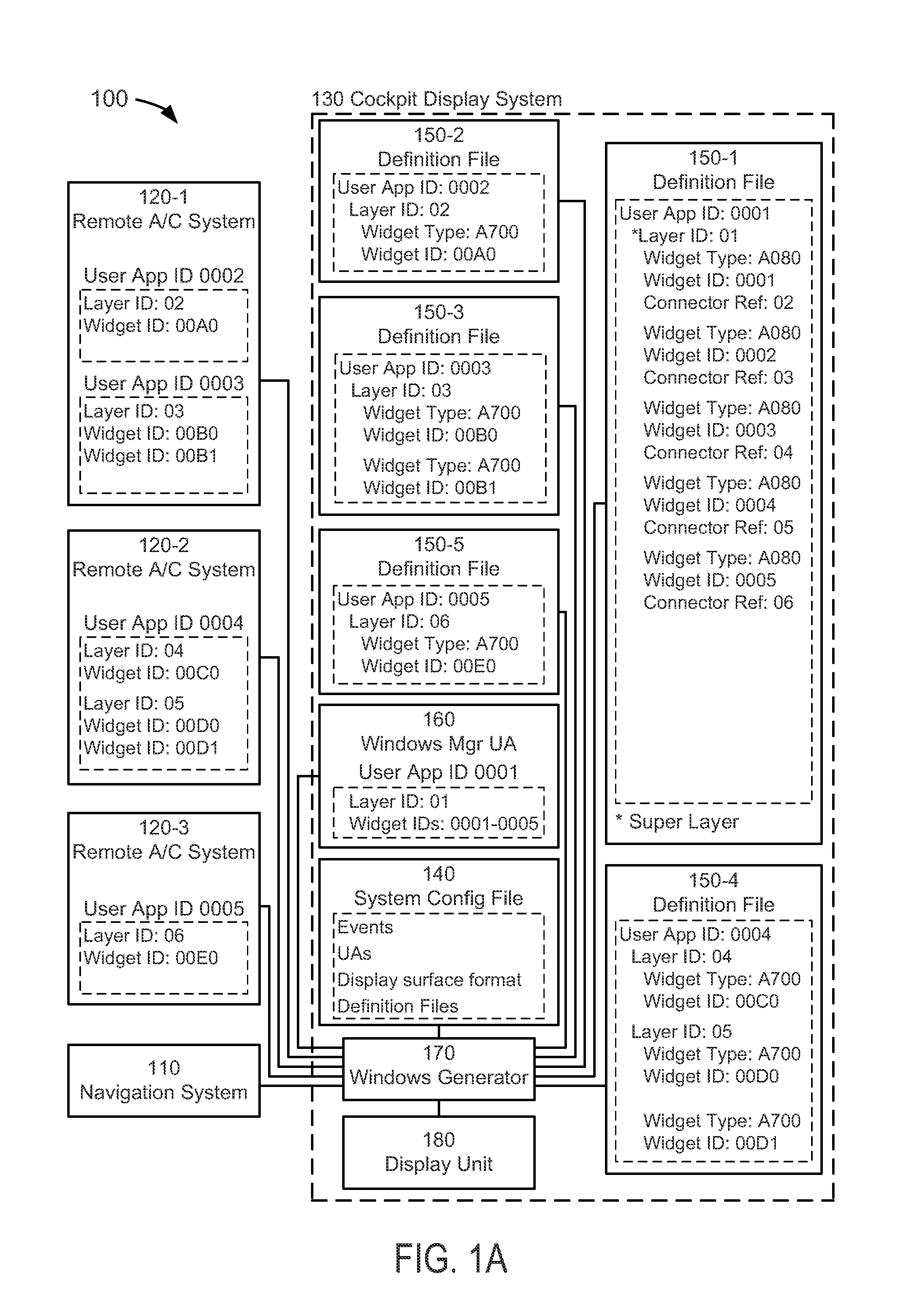
[0027]FIG. 1A depicts a block diagram of an object symbology generating system 100 suitable for implementation of the techniques described herein, wherein object information acquired by a variety of disparate aircraft systems employing different coordinates systems may be sent via one uniform data transmission protocol and used to generate image data representative of objects that is presented on an aircraft display unit(s). The presentation system 100 of an embodiment of FIG. 1A includes a pilot in...


PUM


Abstract

A present novel and non-trivial system, device, and method for generating object symbology are disclosed. A system may be comprised one or more aircraft systems and a cockpit display system comprised of a system configuration file, a plurality of definition files, and a windows generator (“WG”). The WG may be configured to perform initialization and run-time operations. The initialization operation may be comprised of retrieving a system configuration file; retrieving a first definition file comprised of a first layer; and retrieving one or more second definition files comprised of one or more second layers. The run-time operation may be comprised of receiving a first-layer widget data set; receiving one or more second-layer widget data sets; determining the screen position of each object located within a view frustum; and generating a pixel data set in response to the determination.

Description

BACKGROUND OF THE INVENTION[0001]1. Field of the Invention[0002]This invention pertains generally to the field of aircraft display units that provide information to the pilot or flight crew of an aircraft.[0003]2. Description of the Related Art[0004]Aeronautical Radio, Incorporated (“ARINC”) has published ARINC Specification 661 entitled “Cockpit Display System Interfaces to User Systems” (“ARINC 661”), an industry standard which defines an architecture to facilitate a creation of interactive displays. ARINC 661 standardizes the fundamental building blocks of cockpit avionics displays by providing specification that separates graphics from logic, defines a runtime architecture, and defines a communication protocol. The contents of ARINC 661 are known to those skilled in the art.[0005]The Cockpit Display System (“CDS”) may display widgets to the end user, where ARINC 661 specifies a standard set of widgets to develop a cockpit display; a widget may be considered as a displayable enti...

Claims


Application Information

Patent Timeline
IPC IPC(8): G06F7/70
CPCG06F7/70G08G5/0021G01C23/005G08G5/0078G06F8/38
Inventor BULL, IAN J.LAHR, WESTON J.ALBERT, GARY J.HENRY, JEFF M.
Owner ROCKWELL COLLINS INC
Why Eureka
Try Eureka