
Method and apparatus for generating nitric oxide for medical use

a technology for nitric oxide and medical use, applied in the direction of biocide, respirator, drug composition, etc., can solve the problems of not meeting at least one of unable to meet the requirements of a successful portable and safe no generation system, and difficulty in pumping blood through the lungs for oxygenation. , to achieve the effect of low weight, fast and controllable no generation, and low electrical power

Active Publication Date: 2014-07-29
MALLINCKRODT HOSPITAL PRODUCTS IP LTD
View PDF31 Cites 31 Cited by
  • Summary
  • Abstract
  • Description
  • Claims
  • Application Information

AI Technical Summary

Problems solved by technology

In babies with HRF, blood vessels in the lungs constrict, making it difficult for the heart to pump blood through the lungs for oxygenation.
It is important to note that all of the reactants used in this method are hazardous to handle and, accordingly, the process has to be strictly controlled.
Because this method uses cylinder concentrations in the parts per million (ppm) level it requires the use of large pressurized cylinders (approximately 175 mm diameter and 910 mm high with a wetted volume of 16 L and a weight of 18 Kg), which are bulky, heavy, and provide logistical problems and safety requirements associated with the handling of large pressurized gas cylinders.
While these pulse devices allow a compact and low weight delivery device to be made, they still require the bulk and weight of the NO cylinder for NO to be delivered.
Each of the proposed solutions, however, has certain drawbacks in the generation of NO for direct delivery to the patient rather than having to handle the bulk and weight of pressurized gas cylinders and all of the proposed solutions fail to meet at least one of the requirements for a successful portable and safe NO generation system for the immediate delivery of NO to a patient.

Method used


Image

  • Method and apparatus for generating nitric oxide for medical use
  • Method and apparatus for generating nitric oxide for medical use
  • Method and apparatus for generating nitric oxide for medical use

Examples


example 1

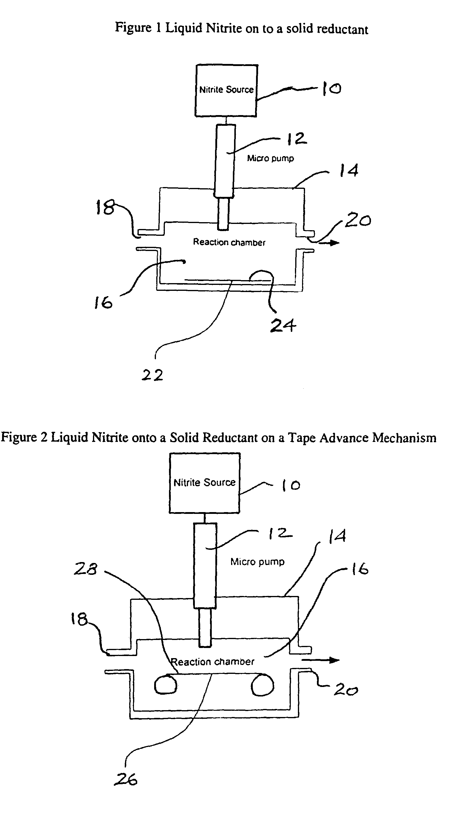
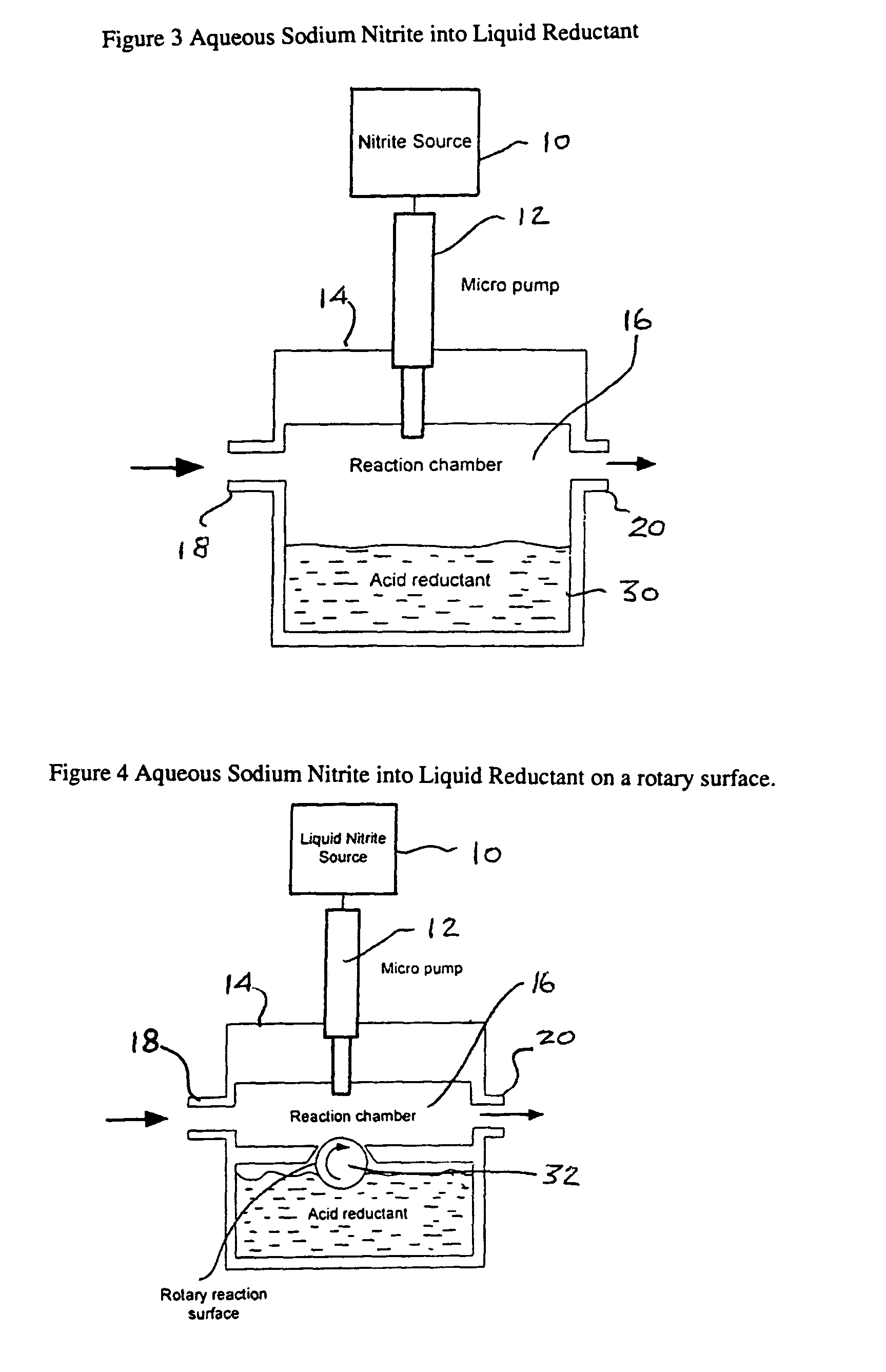
[0065]The first example was carried out using the apparatus of FIG. 3. Aqueous sodium nitrite (1 molar solution) was dispensed directly into a chamber with a reservoir of liquid reductant. The reductant was 1 molar solution of ascorbic acid with 1 molar maleic acid added. The flow through the reaction chamber (Qc) was 0.5 L / min of air and the micro pump delivered 48 nL per pulse every second.

Results:

[0066]Average concentration of NO from the reaction chamber was approximately 123 ppm as shown in FIG. 10.

[0067]The amount of NO being generated can be calculated using Equation 4 where Va is the flow per second in mL given by;

Va=Qc·1000 / 60=0.5·1000 / 60=8.3 ml / sec.

NNO=CNO·10−6·4.16×10−5·Va

NNO=123·4.16·8.3 / 100=42.5 nmoles  Equation 4

[0068]The speed of the reaction wasn't that quick with the NO output not showing distinct pulses but blending into a continuous output. During the test, it was noticeable that the reaction was taking place some distance below the surface of the reductant with ...

example 2

[0069]This next example was carried out with the use of the apparatus of FIG. 4 having a chamber design where the rotary cylinder was used to bring a layer of reductant to the top of the chamber where the aqueous sodium nitrite (1 molar solution) was dispensed onto it. This design was to reduce the delay associated with bubbles of NO forming below the surface of the reductant as seen in Example 1. The flow through the chamber was 0.5 L / min of air and in this case the micro pump was delivering 42 nL per pulse. After each pulse, the rotary reaction surface was rotated to bring fresh reductant to the dispensing means. The rotary reaction surface was roughed up with 400 grip sand paper to provide better reductant retention. The reaction chamber size was also reduced in this design to again speed up the response time of the NO output

Results:

[0070]As can be seen on the chart of FIG. 11, the response time of the reaction was a lot quicker with distinct pulses of NO corresponding to each dr...

example 3

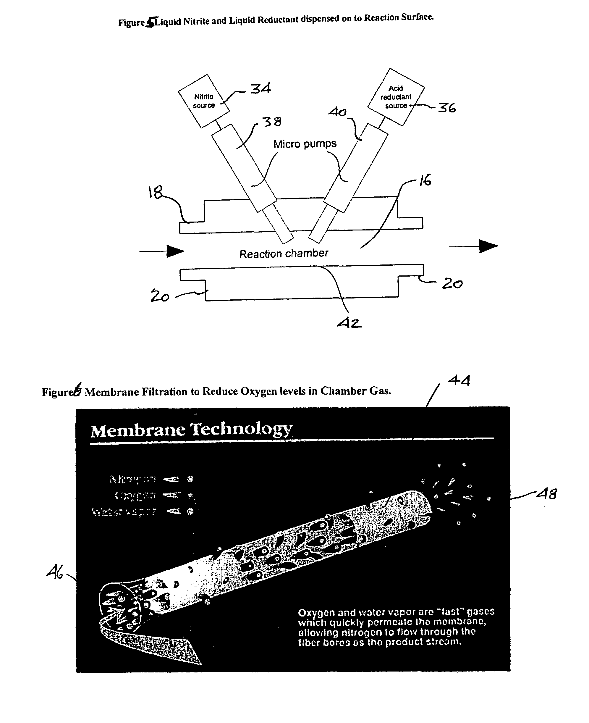
[0071]In this example, both the nitrite and the reductant were dispensed with micro dispensing valves that were configured to deposit the liquid droplets at the same location at the bottom of the reaction chamber. The apparatus was as described in FIG. 5. In this example, the sodium nitrite was a 2 molar solution and the reductant was 1.5 molar solution of ascorbic acid with 0.5 molar maleic acid. The micro pump delivered 42 nL per pulse of sodium nitrate and the second pump delivered 54 nL per pulse of reductant both were pulsed simultaneously every second. The gas flow through the reaction chamber was 0.360 L / min of air.

Results:

[0072]When the system first started up, the output was peaky as in example 2 but as the liquid built up on the reaction chamber floor the output became more like example 1 with the output having a longer reaction time and an average output of NO being delivered. In the slow steady state condition the average output was 385 ppm NO.

[0073]Based on a gas flow o...


PUM


Abstract

A method and system for generating and delivering nitric oxide directly to a patient. A reaction chamber is provided that is located at or in close proximity to the patient and reactants within the reaction chamber react together to produce a predetermined amount of nitric oxide. The reaction is controlled by metering at least one of the reactants into the reaction chamber to generate a predetermined quantity of nitric oxide as required by the patient. The reactants can include a nitrite salt, such as sodium nitrite, and a reductant such as ascorbic acid, maleic acid or a mixture thereof. By generating and delivering the nitric oxide directly to the patient in close proximity thereto, the formation of NO2 is minimized. One or both of the reactants may be in liquid form.

Description

FIELD OF THE INVENTION[0001]The present invention relates to a method and system for generating and administering nitric oxide (NO) to a patient, and, more particularly, to a method and system that generates the NO proximate to and for immediate delivery to the patient.BACKGROUND OF THE INVENTION[0002]The administration of nitric oxide (NO) gas via inhalation for treating patients with pulmonary hypertension is described in Zapol and Frostell's U.S. Pat. No. 5,485,827 “Methods and Devices for Treating Pulmonary Vasoconstriction and Asthma”.[0003]At the present, nitric oxide gas is commonly used for the treatment of persistent pulmonary hypertension in the newborn and is indicated for the treatment of term and near-term (>34 weeks) neonates with hypoxic respiratory failure (HRF) associated with clinical or echocardiographic evidence of pulmonary hypertension. In babies with HRF, blood vessels in the lungs constrict, making it difficult for the heart to pump blood through the lungs...

Claims


Application Information

Patent Timeline
Patent Type & Authority Patents(United States)
IPC IPC(8): A61K33/00A61M16/10
CPCA61M2202/0275A61M16/107A61M2016/102A61K33/00A61M2016/0039A61M16/10A61M2016/0021A61P11/00A61P11/06A61M16/0003A61M16/0057A61M2016/003A61M2205/33
Inventor MONTGOMERY, FREDERICK J.BATHE, DUNCAN P. L.
Owner MALLINCKRODT HOSPITAL PRODUCTS IP LTD
Learn More