
Vehicle structure

a technology for vehicles and suspensions, applied in the direction of roofs, transportation and packaging, vehicle arrangements, etc., to achieve the effect of facilitating the breakage of the rear-portion support member and facilitating the separation of the suspension member

Inactive Publication Date: 2014-08-05
TOYOTA JIDOSHA KK
View PDF16 Cites 24 Cited by
  • Summary
  • Abstract
  • Description
  • Claims
  • Application Information

AI Technical Summary

Benefits of technology

[0007]In view of this, an object of the invention is to provide a vehicle structure that is able to facilitate removal of a suspension member at the time of a vehicle crash.
[0009]According to the vehicle structure of the invention, the suspension member rotates in the vehicle lower direction with a contact portion thereof with the rear-portion support member being taken as a supporting point, due to the impact load toward the vehicle rearward direction. Then, due to latching between the latching member and the rear portion of the suspension member that is displaced in the vehicle lower direction, the load toward the vehicle lower direction is transmitted to the fastening member. Hereby, the impact load toward the vehicle rearward direction and the load toward the vehicle lower direction are efficiently transmitted to the fastening member. As a result, breakage of the rear-portion support member is facilitated, thereby separating the suspension member from the rear-portion support member.
[0010]According to the aspect of the invention, it is possible to provide a vehicle structure that is able to facilitate separating a suspension member at the time of a vehicle crash.

Problems solved by technology

However, in such a vehicle structure, such a problem is assumed that the rear end portion of the suspension member digs deep into the dash panel at the time of the vehicle crash so that the dash panel is largely deformed, thereby preventing the suspension member from separating from the vehicle.

Method used


Image

  • Vehicle structure
  • Vehicle structure
  • Vehicle structure

Examples


Embodiment Construction

[0018]The following specifically describes a vehicle structure according to an embodiment of the invention with reference to the attached drawings. Note that the same elements in the description of the drawings have the same reference sign and redundant description thereof is omitted.

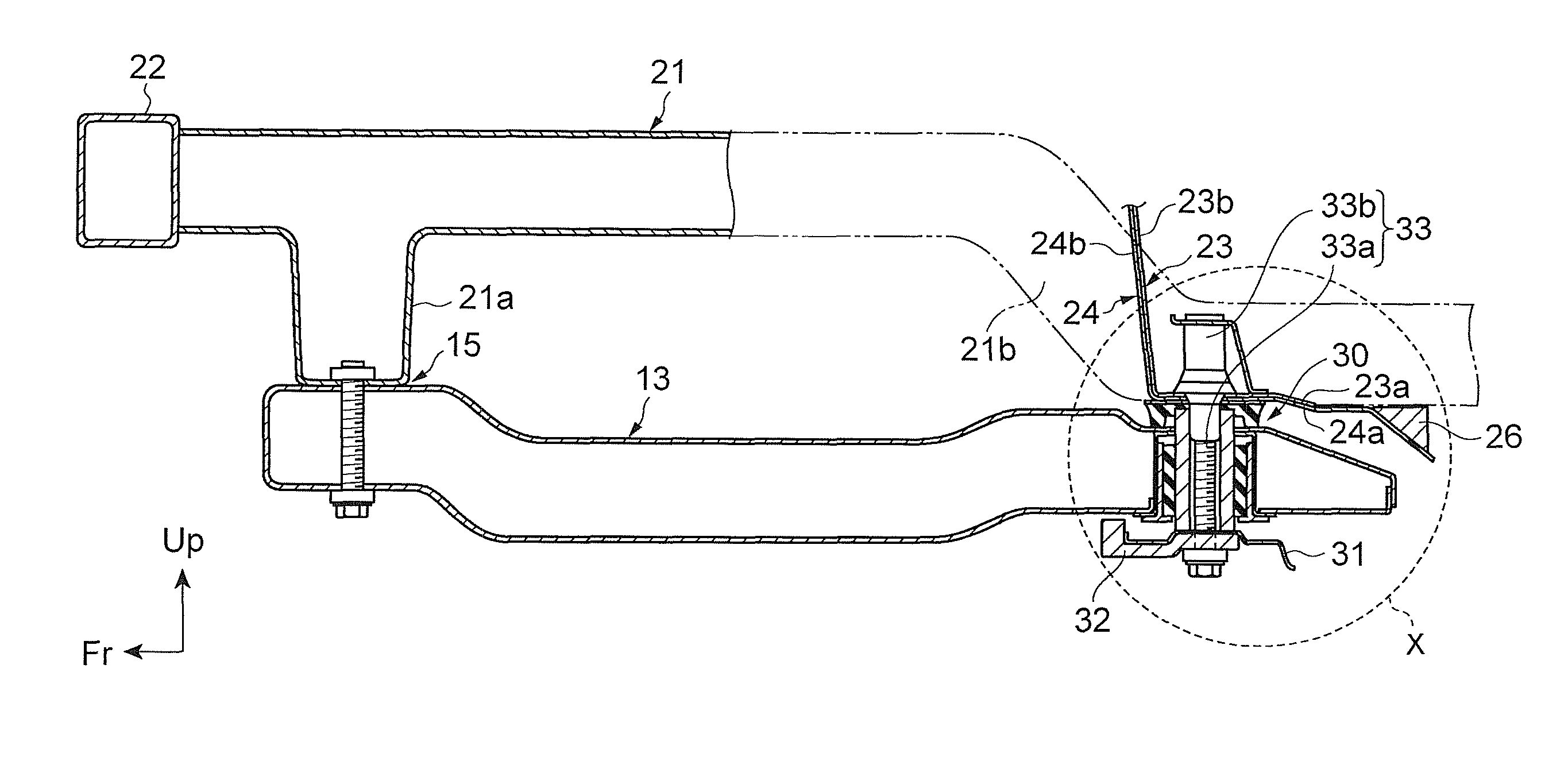
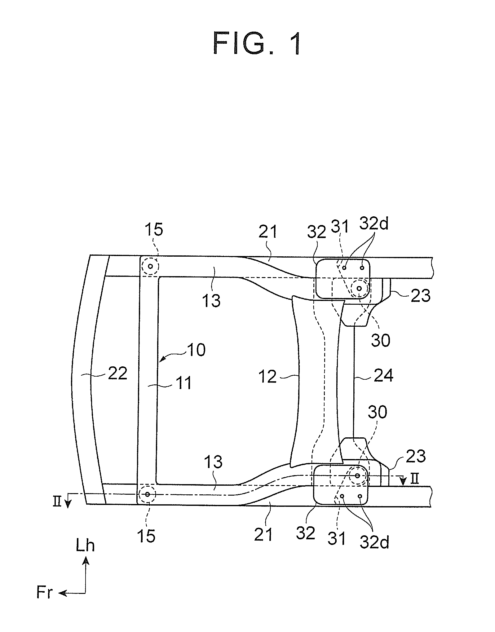
[0019]Initially described is a configuration of the vehicle structure according to the embodiment of the invention with reference to FIGS. 1 to 3. FIG. 1 is a bottom plan view illustrating a structure for fastening a suspension member 10 in a vehicle front portion.

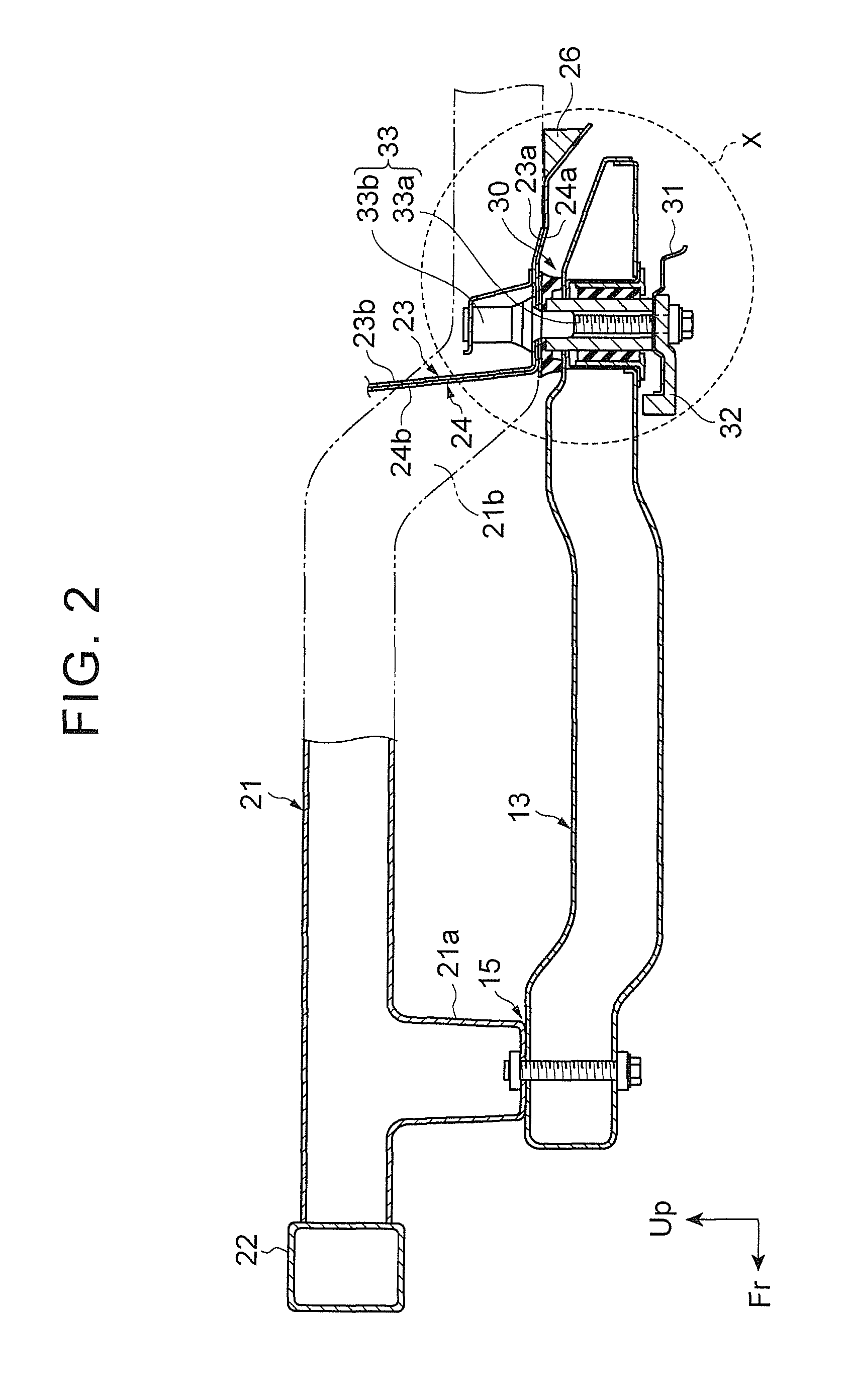
[0020]FIG. 2 is a sectional view taken along a line II-II in FIG. 1. Note that, in FIGS. 1 and 2, an arrow Fr indicates a vehicle front side, an arrow Lh indicates a vehicle left side, and an arrow Up indicates a vehicle upper side.

[0021]As illustrated in FIGS. 1 and 2, in the vehicle front portion, the suspension member 10 for supporting a suspension mechanism of a vehicle is provided. Above the suspension member 10 (on a depth side in FIG. 1...


PUM


Abstract

A vehicle structure includes: a suspension member for supporting a suspension mechanism of a vehicle; a rear-portion support member (inner members, a dash panel) provided above a rear portion of the suspension member and supporting the suspension member; a fastening member for fastening the rear portion of the suspension member to the rear-portion support member; and a latching member provided in the fastening member and latching thereto the rear portion of the suspension member to be displaced in a vehicle lower direction due to an impact load toward a vehicle rearward direction, so as to transmit, to the fastening member, a load toward the vehicle lower direction.

Description

INCORPORATION BY REFERENCE[0001]The disclosure of Japanese Patent Application No. 2013-008597 filed on Jan. 21, 2013 including the specification, drawings and abstract is incorporated herein by reference in its entirety.BACKGROUND OF THE INVENTION[0002]1. Field of the Invention[0003]The invention relates to a vehicle structure, more particularly to a structure for fastening a suspension member in a vehicle front portion.[0004]2. Description of Related Art[0005]As a vehicle structure, Japanese Patent Application Publication No. 2012-45995 (JP2012-45995 A) describes a structure in which a rear end portion of a suspension member is provided close to a dash panel so as to facilitate a bending rotation of the suspension member at the time of a vehicle crash.[0006]However, in such a vehicle structure, such a problem is assumed that the rear end portion of the suspension member digs deep into the dash panel at the time of the vehicle crash so that the dash panel is largely deformed, thereb...

Claims


Application Information

Patent Timeline
Patent Type & Authority Patents(United States)
IPC IPC(8): B62D21/02
CPCB62D21/155B60G2204/41B60G7/02B60G2204/15B60G2206/0114B60G2206/60
Inventor ONISHI, KOJIHONSHO, TOMOYUKI
Owner TOYOTA JIDOSHA KK
Learn More