Instrument docking station for an automated testing system

a technology of automated testing and instrument docking station, which is applied in the field of life sciences industry, can solve the problems of affecting the future integration of additional laboratory devices and the repair and/or upgrading of laboratory devices, affecting the quality of instrument docking station, etc., and achieving the effect of reducing the number of instruments and reducing the number of tests

Active Publication Date: 2014-08-05
HIGHRES BIOSOLUTIONS INC
View PDF27 Cites 11 Cited by
  • Summary
  • Abstract
  • Description
  • Claims
  • Application Information

AI Technical Summary

Problems solved by technology

As a first shortcoming, the above-described method of permanently securing an automated laboratory device to a particular surface greatly inhibits both (i) the future integration of additional laboratory devices and (ii) the repair and / or upgrading of the laboratory device.
As a consequence, it has been found that the effective life of the automated system is minimized, which is highly undesirable.
As a second shortcoming, the above-described method of performing numerous, individualized, manual input connections into each automated laboratory device renders the entire installation process (i.e., system set-up) time-consuming, cumbersome and complex in nature, which is highly undesirable.
As a third shortcoming, the above-described method of permanently securing an automated laboratory device to a particular surface renders the device unavailable for use in conjunction with alternate testing throughout the lifespan of the system.
Because certain laboratory devices are expensive to purchase, the inability to use a single laboratory device in conjunction with multiple simultaneous experiments substantially increases the costs incurred at a life science research facility, which is highly undesirable.

Method used


Image

  • Instrument docking station for an automated testing system
  • Instrument docking station for an automated testing system
  • Instrument docking station for an automated testing system

Examples


Embodiment Construction

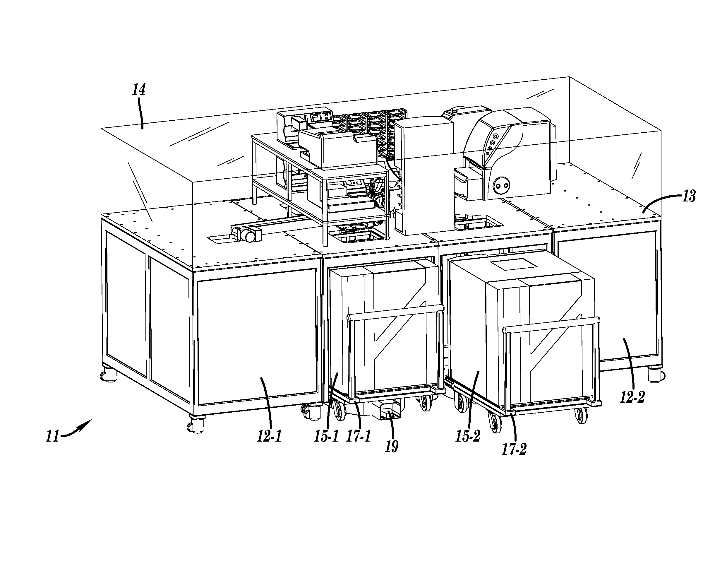
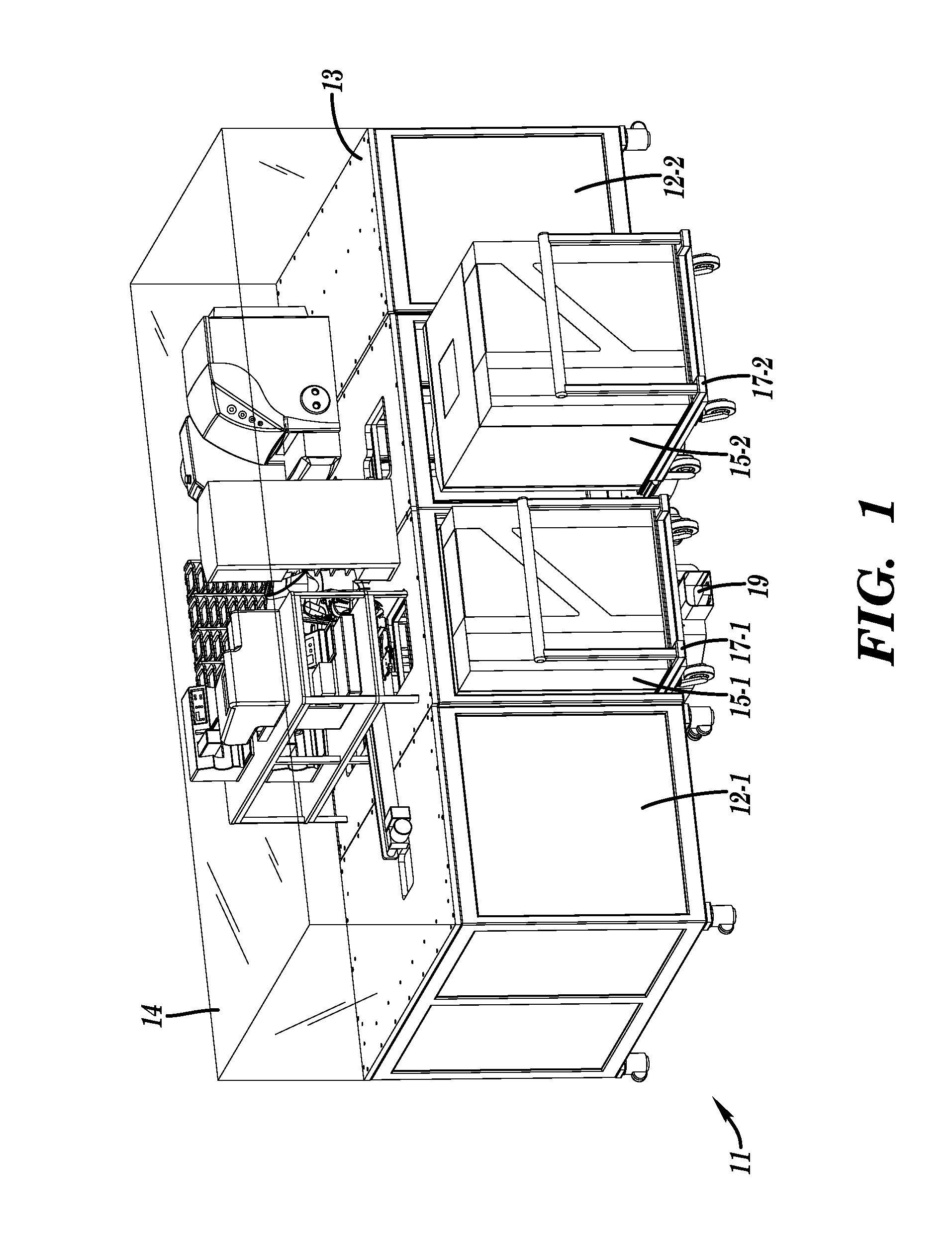
[0038]Referring now to FIG. 1, there is shown an automated testing system that is constructed according to the teachings of the present invention, said automated testing system being identified generally by reference numeral 11. As can be appreciated, system 11 is designed principally for use in conducting laboratory research in the life sciences industry and may be used, more specifically, to perform high throughput screening (HTS) in the life sciences industry.

Automated Testing System (11)

[0039]System 11 comprises a pair of fixedly mounted end units 12-1 and 12-2 which together support a flat table surface 13 on which certain laboratory devices are fixedly mounted. Preferably, a transparent testing chamber 14 is mounted on table surface 13 over said devices in order to provide an enclosed testing environment that may be regulated by the operator to optimize results.

[0040]System 11 additionally includes a pair of automated laboratory devices 15-1 and 15-2 that are configured to be ...


PUM

PropertyMeasurementUnit
degree of displacementaaaaaaaaaa
timeaaaaaaaaaa
electricalaaaaaaaaaa

Abstract

An automated testing system includes one or more laboratory devices that operate together to perform an assay. The testing system is designed such that a laboratory device may be seamlessly integrated with the remaining devices in a quick and effortless manner. Specifically, the laboratory device is securely mounted on a slidable cart with fluid and electrical connections established therebetween. The slidable cart is in turn adapted to releasably engage with a docking station that is fixedly mounted on the workspace floor, the docking station being provided with at least one fluid input connection, an input power connection and at least one communication signal connection that are relatively permanent in nature. In order to couple the cart to the docking station, the cart is rolled generally into position above the docking station using complementary alignment posts and tracks.

Description

[0001]This application is a continuation-in-part patent application of U.S. patent application Ser. No. 11 / 394,373, filed on Mar. 29, 2006 now U.S. Pat. No. 7,560,071.BACKGROUND OF THE INVENTION[0002]The present invention relates generally to the life sciences industry and more particularly to automated testing systems for conducting high throughput screening in the life sciences industry.[0003]High throughput screening (HTS) is a well-known form of scientific experimentation in the life sciences industry which enables a research facility to conduct a large quantity of experiments at the same time. Specifically, in one form of high throughput screening which is well-known in the art, a plate is provided which includes a large number of isolated, miniaturized wells (e.g., 96, 384 or 1536 wells per plate), whereby a unique compound is disposed within each well. An array of different substances is then deposited into each well with the premise of discovering a desired reaction. In this...

Claims


Application Information

Patent Timeline
Patent Type & Authority Patents(United States)
IPC IPC(8): G01N35/00B01L3/00B01L9/02G01N35/04
CPCB01L9/02B01L3/565G01N35/04Y10T436/11Y10T436/113332Y10T436/111666
Inventor NICHOLS, MICHAEL J.GUARRACINA, LOUIS J.
Owner HIGHRES BIOSOLUTIONS INC
Why Eureka
Try Eureka