Light-enhancing structure for electrophoretic display

a technology of electrophoretic display and light-enhancing structure, which is applied in the direction of optics, instruments, optical elements, etc., can solve the problems of significant influence on the quality of the images displayed

Active Publication Date: 2014-08-05
E INK CORPORATION
View PDF117 Cites 61 Cited by
  • Summary
  • Abstract
  • Description
  • Claims
  • Application Information

AI Technical Summary

Benefits of technology

[0009](c) electrodes on the second substrate layer which can drive the display fluid laterally.

Problems solved by technology

One of the disadvantages of the lateral switching method is that the colors displayed may appear washed-out under sun light, which would significantly impact on the quality of the images displayed.

Method used


Image

  • Light-enhancing structure for electrophoretic display
  • Light-enhancing structure for electrophoretic display
  • Light-enhancing structure for electrophoretic display

Examples


Embodiment Construction

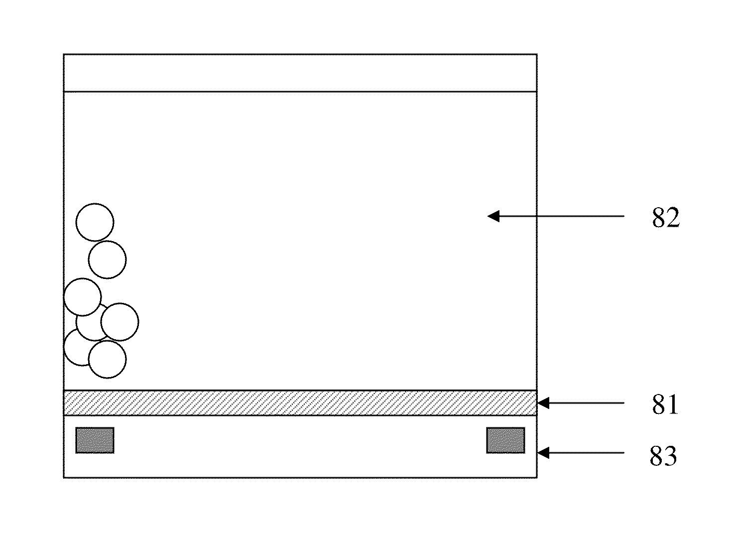
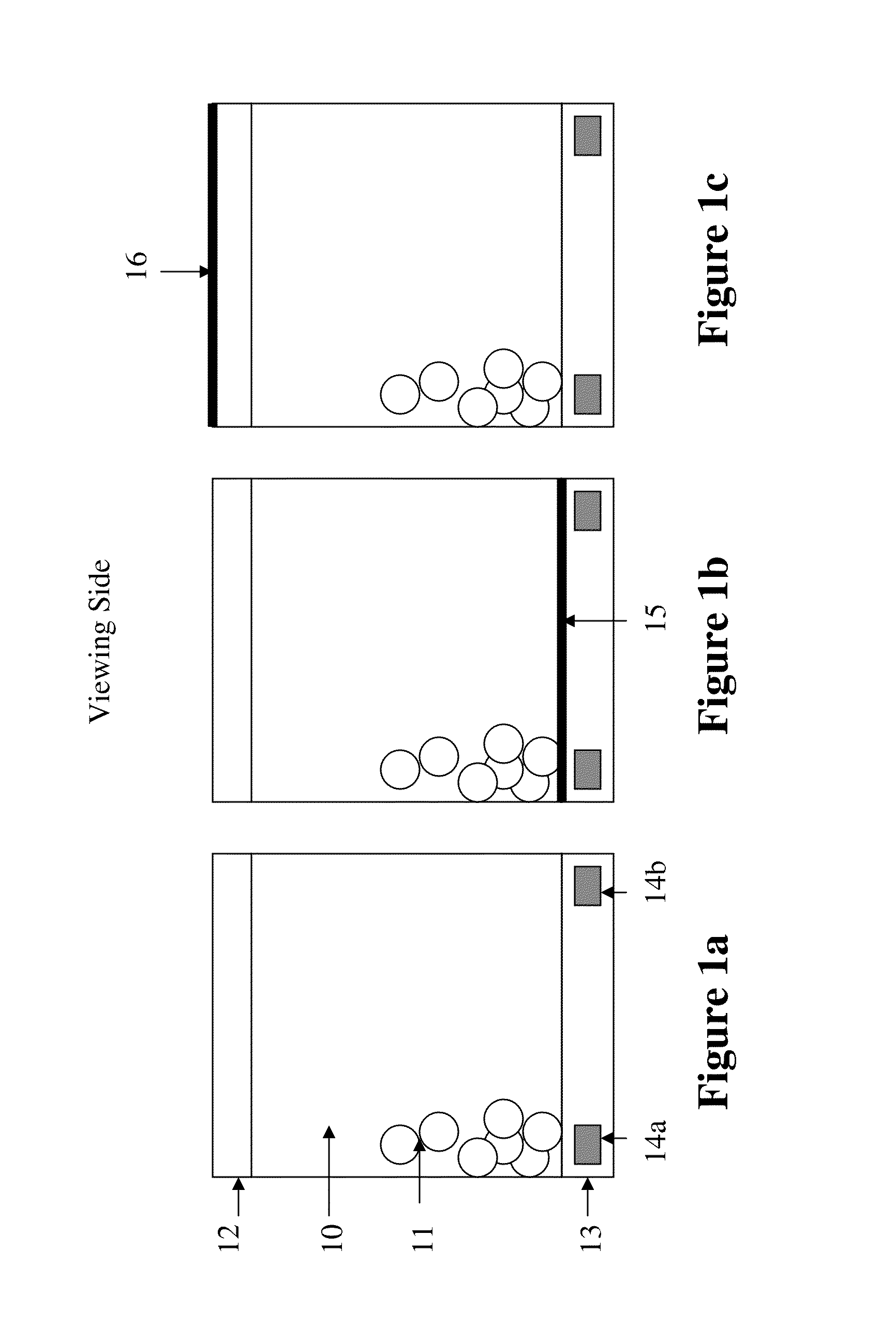
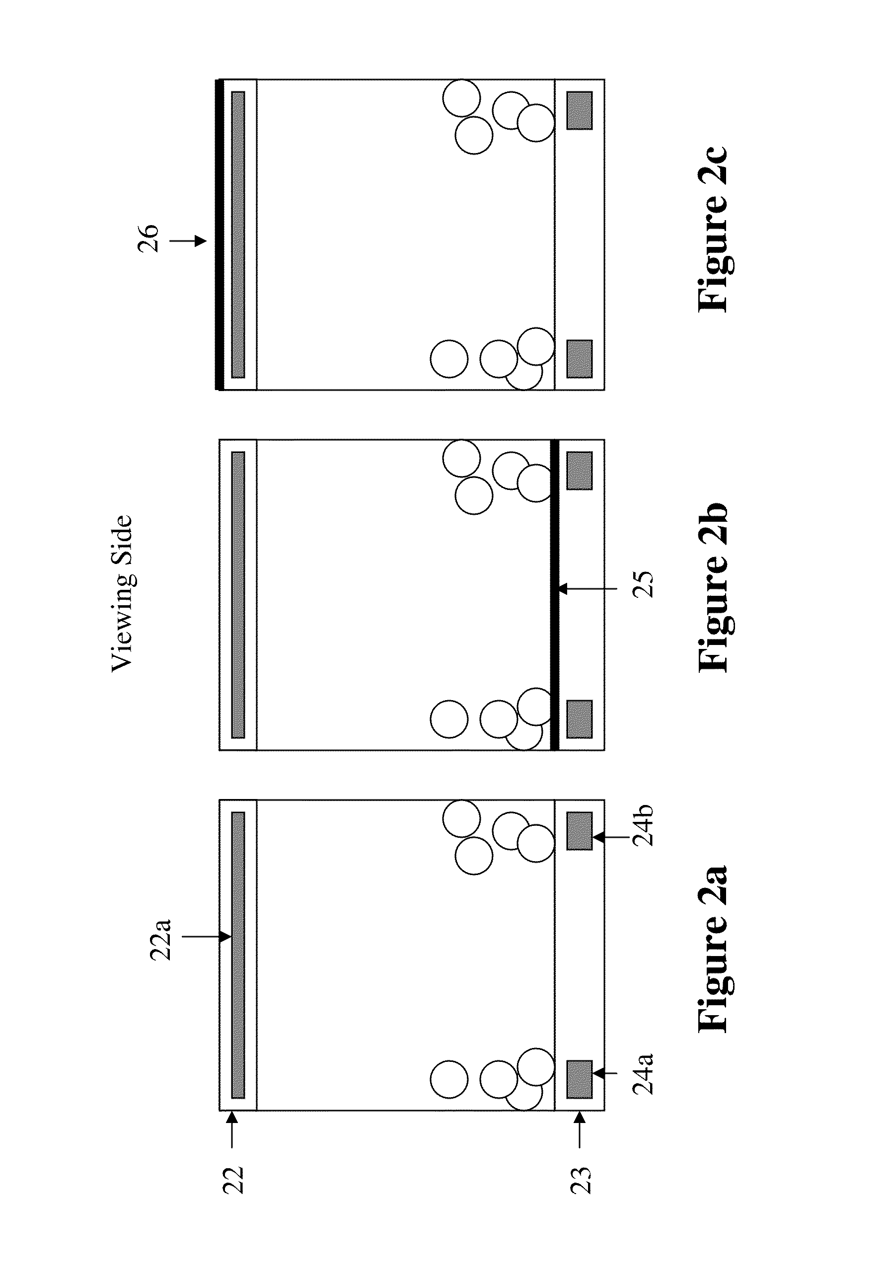
[0026]FIGS. 1-7 illustrate examples of how an electrophoretic display is structured with lateral switching of the charged pigment particles.

[0027]In FIG. 1a, a display fluid (10) comprising only one type of charged pigment particles (11) is sandwiched between a first substrate layer (12) and a second substrate layer (13) comprising two in-plane electrodes (14a and 14b). When a proper voltage potential difference is imposed between the two in-plane electrodes, the charged pigment particles would move to be near or at one of the in-plane electrodes. Therefore in this case, the color of the solvent in which the charged pigment particles are dispersed is seen from the viewing side.

[0028]In FIG. 1b, the design is similar to that in FIG. 1a, except that there is a color layer (15) on top of the second substrate layer (13). The color layer may be a color adhesive layer. In this case, the color seen from the viewing side would be a composite color of the solvent and the color layer.

[0029]Wh...


PUM

PropertyMeasurementUnit
refractive indexaaaaaaaaaa
diameteraaaaaaaaaa
refractive indicesaaaaaaaaaa

Abstract

The present invention is directed to a display device comprising a display fluid layer sandwiched between a first substrate layer and a second substrate layer, and a light-enhancing layer between the display fluid layer and the second substrate layer. The light-enhancing structure can enhance the colors displayed by the display device, especially the colors displayed through lateral switching of the charged pigment particles in an electrophoretic fluid.

Description

FIELD OF THE INVENTION[0001]The present invention is directed to a light-enhancing structure for an electrophoretic display device. The light-enhancing structure can enhance the colors displayed by the display device, especially the colors displayed through lateral switching of the charged pigment particles in an electrophoretic fluid.BACKGROUND OF THE INVENTION[0002]The electrophoretic display (EPD) is a non-emissive device based on the electrophoresis phenomenon of charged pigment particles dispersed in a solvent. The display typically comprises two plates with electrodes placed opposing each other. One of the electrodes is usually transparent. An electrophoretic fluid composed of a colored solvent with charged pigment particles dispersed therein is enclosed between the two plates. When a voltage difference is imposed between the two electrodes, the pigment particles migrate to one side or the other causing either the color of the pigment particles or the color of the solvent bein...

Claims


Application Information

Patent Timeline
Patent Type & Authority Patents(United States)
IPC IPC(8): G02B26/00G02F1/167G02F1/1677
CPCG02F1/167G02F2203/02G02F2203/03G02F1/1677
Inventor YANG, BO-RUHSIEH, YAO-JEN
Owner E INK CORPORATION
Why Eureka
Try Eureka