Fluid dispenser

a dispenser and flue technology, applied in the field of flue dispensers, can solve the problem that the dispenser is rarely provided with a repositionable closure member, and achieve the effect of convenient uncovered

Inactive Publication Date: 2014-08-12
APTAR FRANCE SAS
View PDF9 Cites 2 Cited by
  • Summary
  • Abstract
  • Description
  • Claims
  • Application Information

AI Technical Summary

Benefits of technology

[0006]An object of the present invention is to remedy the above-mentioned drawback of the prior art by defining a fluid dispenser having a dispenser orifice that may easily be uncovered, and then closed once again, and to do so repeatedly.
[0007]To achieve this object, the present invention proposes a fluid dispenser comprising: a flexible pouch that comprises two flexible sheets that define between them a fluid reservoir and an opening; and a stopper-and-dispenser member that is mounted in stationary, permanent, and leaktight manner in the opening of the pouch, the stopper member including a body that defines a dispenser orifice, an outlet channel that connects the reservoir to the dispenser orifice, and two sealing zones, respectively for the two flexible sheets of the pouch; the dispenser being characterized in that the stopper-and-dispenser member further includes a closure lid for closing the dispenser orifice, the lid being hinged on the body in such a manner as to pivot between a closed position and an open position. The use of a pivotable closure lid is completely unusual for this type of dispenser presenting an extremely flat configuration. With the pivotable closure lid, it is very easy to uncover the dispenser orifice, and to close it once again, and to do so repeatedly.
[0011]Advantageously, the flap is attached to the pouch on either side of the stopper member and includes a notch in which the lid is arranged. The lid is indeed arranged in the notch, but it is impossible to actuate it as a result of the small size of the notch. It can be said that the notch surrounds the lid.Advantageously, the lid pivots in a plane, the flap extending in said plane above the lid preventing it from pivoting, the flap being movable out from the plane so as to release the lid, the flap advantageously being hinged on the pouch and being formed by the two flexible sheets connected together. The flap may further include a suspension slot making it possible to hang the dispenser on a pin of a display.

Problems solved by technology

However, as a result of it being a dispenser that is nearly always used once only, that type of dispenser is rarely provided with a repositionable closure member.

Method used


Image

  • Fluid dispenser
  • Fluid dispenser
  • Fluid dispenser

Examples


Embodiment Construction

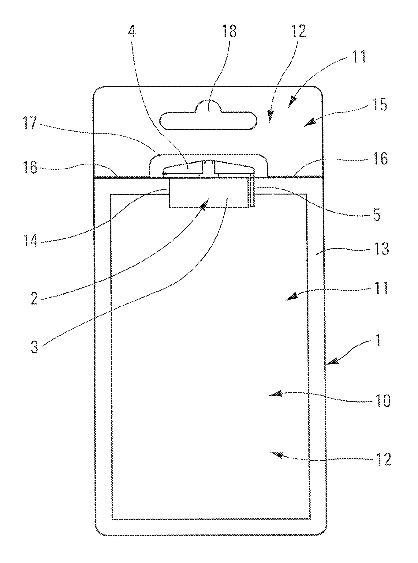
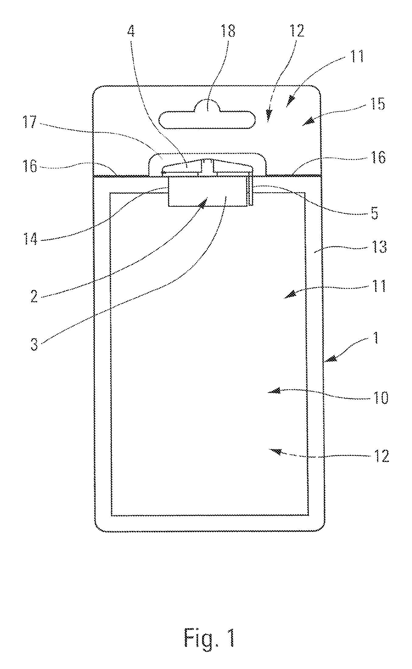
[0022]Reference is made firstly to FIG. 1 in order to describe in general the structure of a fluid dispenser made in accordance with the invention. The dispenser comprises two essential component elements, namely: a fluid reservoir 10; and a stopper-and-dispenser member 2 that is suitable for dispensing the fluid stored in the fluid reservoir 10. Optionally, the dispenser includes a flap 15 that is preferably associated with the fluid reservoir 10.

[0023]The fluid reservoir 10 is constituted by a flexible pouch 1 that comprises two flexible sheets 11, 12 that are connected together at their outer peripheries 13, except at an opening 14. By way of example, the two flexible sheets 11, 12 may be formed from a laminate of aluminum and plastics material. The two sheets 11, 12 are preferably assembled together by heat-sealing. The opening 14 is closed by the stopper-and-dispenser member 2, the detailed structure of which is described below. By way of example, the flexible sheets 11, 12 may...


PUM

PropertyMeasurementUnit
thicknessaaaaaaaaaa
heightaaaaaaaaaa
heightaaaaaaaaaa

Abstract

A fluid dispenser comprising:a flexible pouch (1) that comprises two flexible sheets (11, 12) that define between them a fluid reservoir (10) and an opening (14); anda stopper-and-dispenser member (2) that is mounted in stationary, permanent, and leaktight manner in the opening (14) of the pouch (1), the stopper member (2) including a body (3) that defines a dispenser orifice (34) and two sealing zones (31c, 31d), respectively for the two flexible sheets (11, 12) of the pouch (1);the dispenser being characterized in that the stopper-and-dispenser member (2) further includes a closure lid (4) for closing the dispenser orifice (34), the lid (4) being hinged (43) on the body (3) in such a manner as to pivot between a closed position and an open position.

Description

CROSS REFERENCE TO RELATED APPLICATION[0001]This application claims the benefit under 35 U.S.C. §119(e) of pending U.S. provisional patent application Ser. No. 61 / 552,583, filed Oct. 28, 2011, and priority under 35 U.S.C. §119(a)-(d) of French patent application No. FR-11.59392, filed Oct. 18, 2011.TECHNICAL FIELD[0002]The present invention relates to a fluid dispenser comprising a stopper-and-dispenser member that is associated with a flexible pouch that defines a fluid reservoir and an opening in which the stopper-and-dispenser member is mounted in stationary, permanent, and leaktight manner. The flexible pouch generally comprises two flexible sheets that are sealed in leaktight manner on two respective sealing zones that are formed by the stopper-and-dispenser member. The stopper-and-dispenser member includes an outlet channel that connects the reservoir of the pouch to a dispenser orifice. Such a fluid dispenser finds an advantageous application in the fields of cosmetics, pharm...

Claims


Application Information

Patent Timeline
Patent Type & Authority Patents(United States)
IPC IPC(8): B65D33/14B65D33/10B65D33/16B65D35/00B65D47/00
CPCB65D73/0064B65D75/30B65D75/5883B65D2101/0015B65D2575/586B65D2401/10
Inventor CROIBIER, DENISPIERRE, CHRISTOPHE
Owner APTAR FRANCE SAS
Why Eureka
Try Eureka