
Connector bracket

a technology for connecting brackets and devices, which is applied in the direction of electrical apparatus contruction details, coupling device connections, and electrical apparatus casings/cabinets/drawers, etc. it can solve the problems of increasing the internal space of the device enclosure. , to achieve the effect of preventing deformation of the device enclosure and reducing damage/breakag

Inactive Publication Date: 2014-08-12
APPLE INC
View PDF27 Cites 20 Cited by
  • Summary
  • Abstract
  • Description
  • Claims
  • Application Information

AI Technical Summary

Benefits of technology

The patent describes using trim rings or brackets to reinforce electronic device housings and prevent damage from plug connectors. These brackets are made from strong materials that can withstand repeated contact with plug connectors and are designed to spread loads over a larger surface area of the device housing. The technical effect of this invention is to increase the durability and reliability of electronic devices while still maintaining their efficiency and functionality.

Problems solved by technology

In response to the demand for smaller and lighter electronic devices, device enclosures have increasingly limited internal space while still including a large number of internal components.
Limited space within the enclosures of devices creates a number of challenges.
For example, the limited internal space of these enclosures drives the demand for smaller internal components such as smaller receptacle connectors for receiving smaller corresponding plug connectors.
However, smaller receptacle connectors may be prone to breaking due to thinner receptacle connectors walls, particularly when made from polymers.
In addition, lighter electronic devices may include housings that are made from lighter, less robust materials that may also be prone to being damaged and / or breaking.
Damage to these receptacle connectors and / or device housings may occur during normal use of devices or when plug connectors are improperly inserted into and / or extracted from receptacle connectors and device housings.
This may create additional challenges.

Method used


Image

  • Connector bracket
  • Connector bracket
  • Connector bracket

Examples


Embodiment Construction

[0060]The present invention will now be described in detail with reference to certain embodiments thereof as illustrated in the accompanying drawings. In the following description, numerous specific details are set forth in order to provide a thorough understanding of the present invention. It will be apparent, however, to one skilled in the art, that the present invention may be practiced without some or all of these specific details. In other instances, well known details have not been described in detail in order not to unnecessarily obscure the present invention.

[0061]As discussed earlier, the invention may apply to a variety of different electronic devices, which may use a variety of different connector technologies. Accordingly, this invention may be used with many electronic devices that mate with a variety of electrical connectors in order to receive and provide power and data. Examples of electronic devices that may include the present invention are shown in the following f...


PUM


Abstract

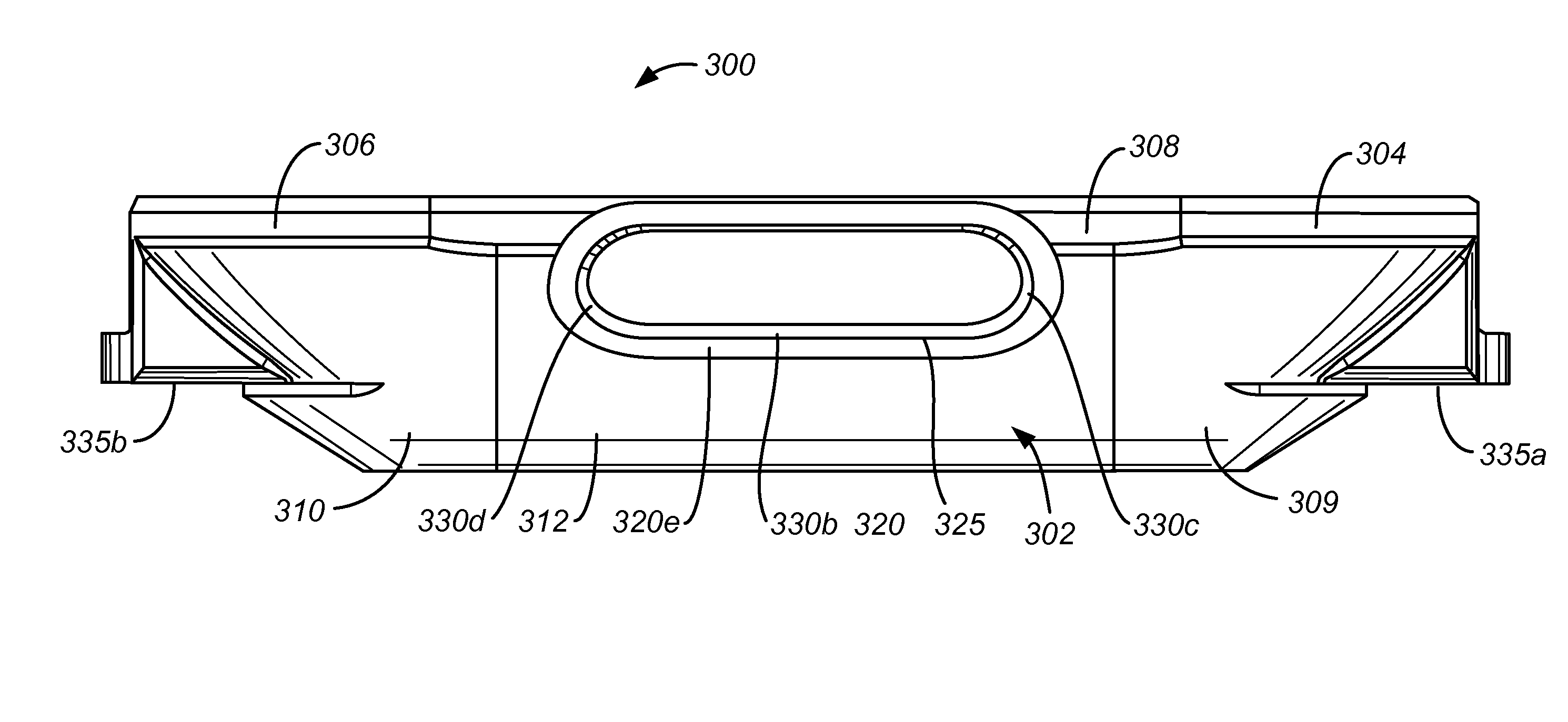
Brackets may be mated with or coupled to an opening of an electronic device enclosure or housing for receiving plug connectors to reinforce the receptacle connector and / or device housing and potentially reduce damage / breakage. For example, a bracket can have a front face with a curvature. A back face of the bracket can include a first opening that communicates with a cavity. The cavity can be defined at least in part by upper and lower opposing inner surfaces, the lower inner surface including a portion that extends parallel to a portion of the bracket front face. The bracket can also include a hollow protrusion extending from the bracket front face in a front direction. The hollow protrusion can include an opening that communicates with the opening of the back face and extends through the hollow protrusion. Methods for manufacturing the connector bracket are also provided.

Description

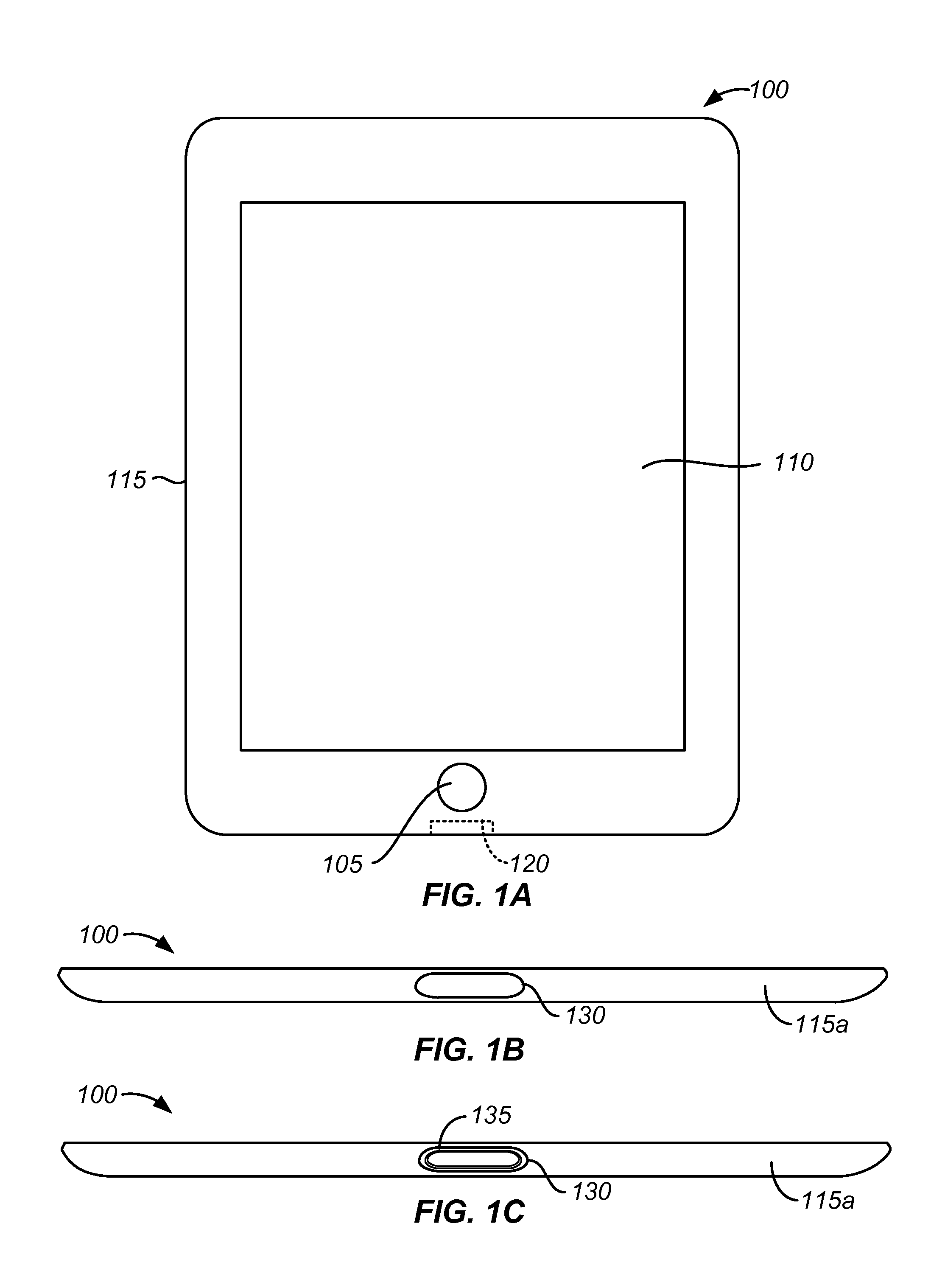
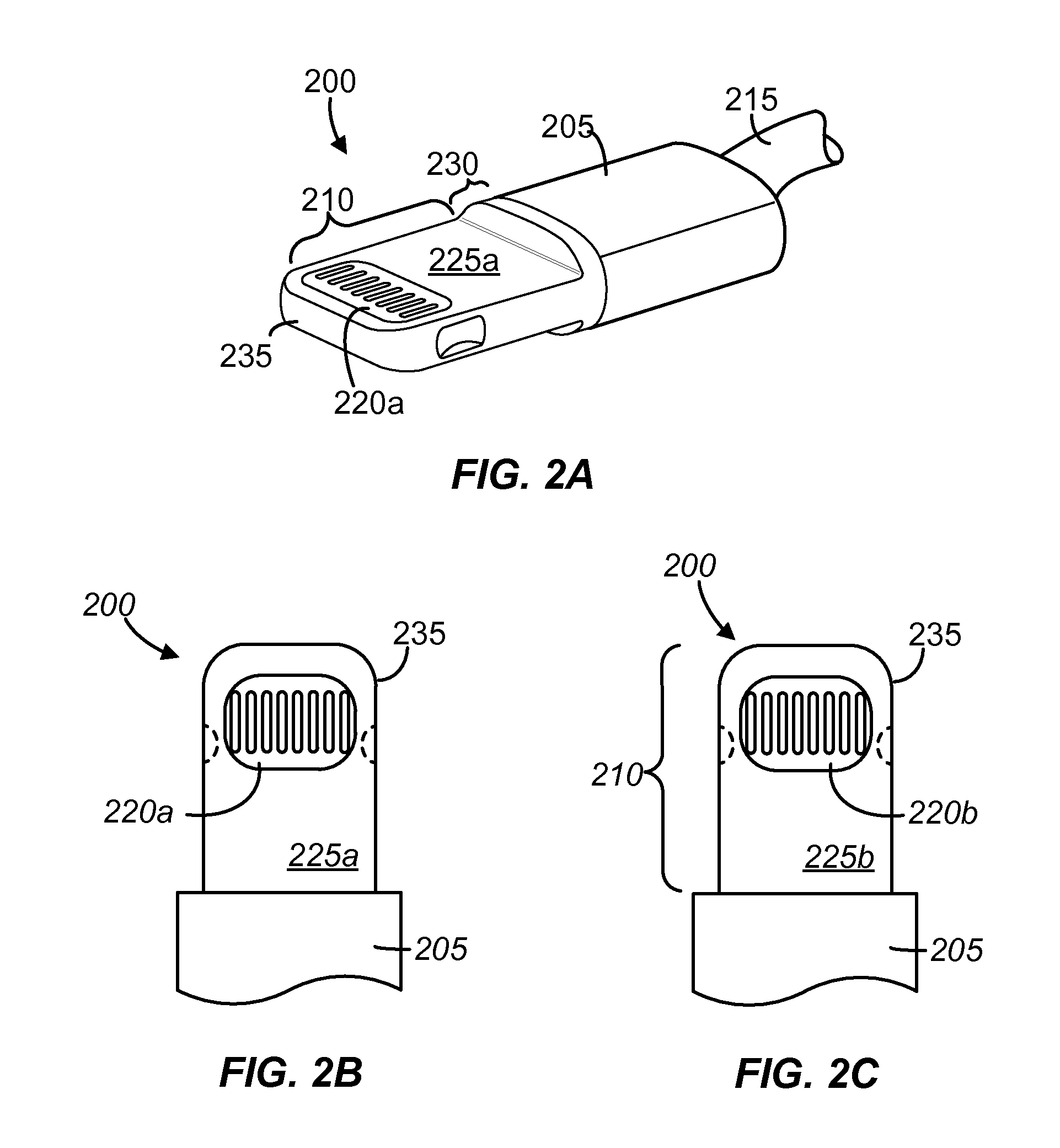
CROSS REFERENCE TO RELATED APPLICATIONS[0001]This application is a non-provisional, claiming benefit under 35 U.S.C. §119(e), of U.S. Patent Application No. 61 / 699,818 filed Sep. 11, 2012 for “Connector Trim”. The entire disclosure of the above mentioned application is incorporated by reference for all purposes.BACKGROUND OF THE INVENTION[0002]The present invention relates generally to electronic device enclosures or housings, and in particular the interface between electronic device housings and electrical connectors.[0003]Many electronic devices include electrical connectors that receive and provide power and data. For example, devices, such as tablets, laptops, netbooks, desktops, and all-in-one computers; cell, smart, and media phones; storage devices, portable media players, navigation systems, monitors, and others, use electrical connectors for power and / or data. These electrical connectors are typically receptacle connectors and are designed to receive a male plug connector. ...

Claims


Application Information

Patent Timeline
Patent Type & Authority Patents(United States)
IPC IPC(8): H05K5/00H02G15/007
CPCH02G15/007H01R13/516H01R13/74
Inventor UTTERMANN, ERIK A.RAFF, JOHNTRZASKOS, PIOTR S.
Owner APPLE INC
Learn More