Lamp changers

a technology for changing lights and lamps, applied in the direction of electrical equipment, climate sustainability, installation/removing discharge tubes/lamp auxiliary devices, etc., can solve the problems of increasing the complexity of a cfl changer, the inability to install or change cfls in high places, and the inability to use devices designed for installing regular incandescent light bulbs

Inactive Publication Date: 2014-08-19
BELL MARK
View PDF43 Cites 3 Cited by
  • Summary
  • Abstract
  • Description
  • Claims
  • Application Information

AI Technical Summary

Benefits of technology

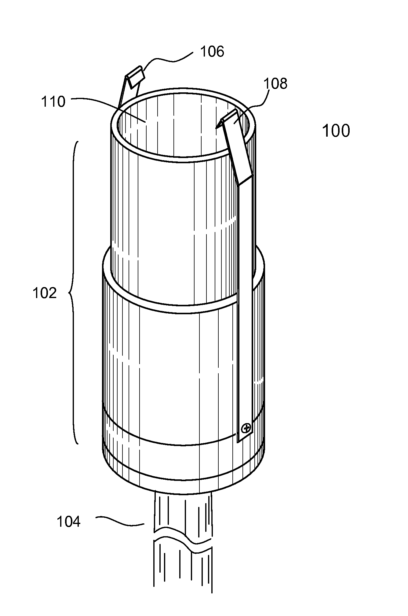
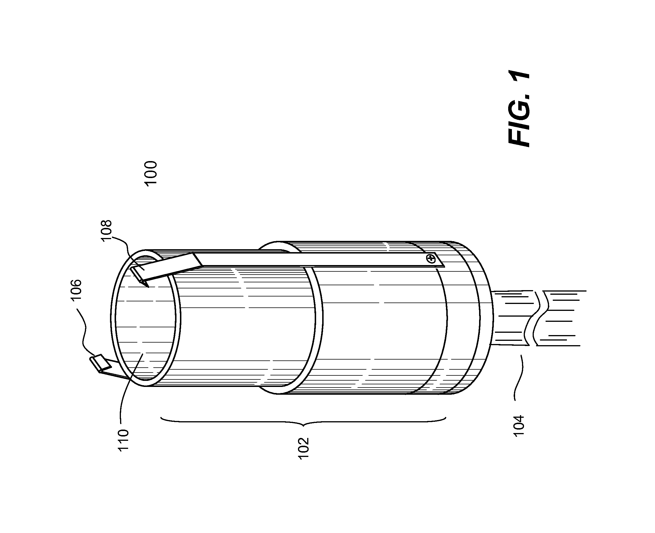
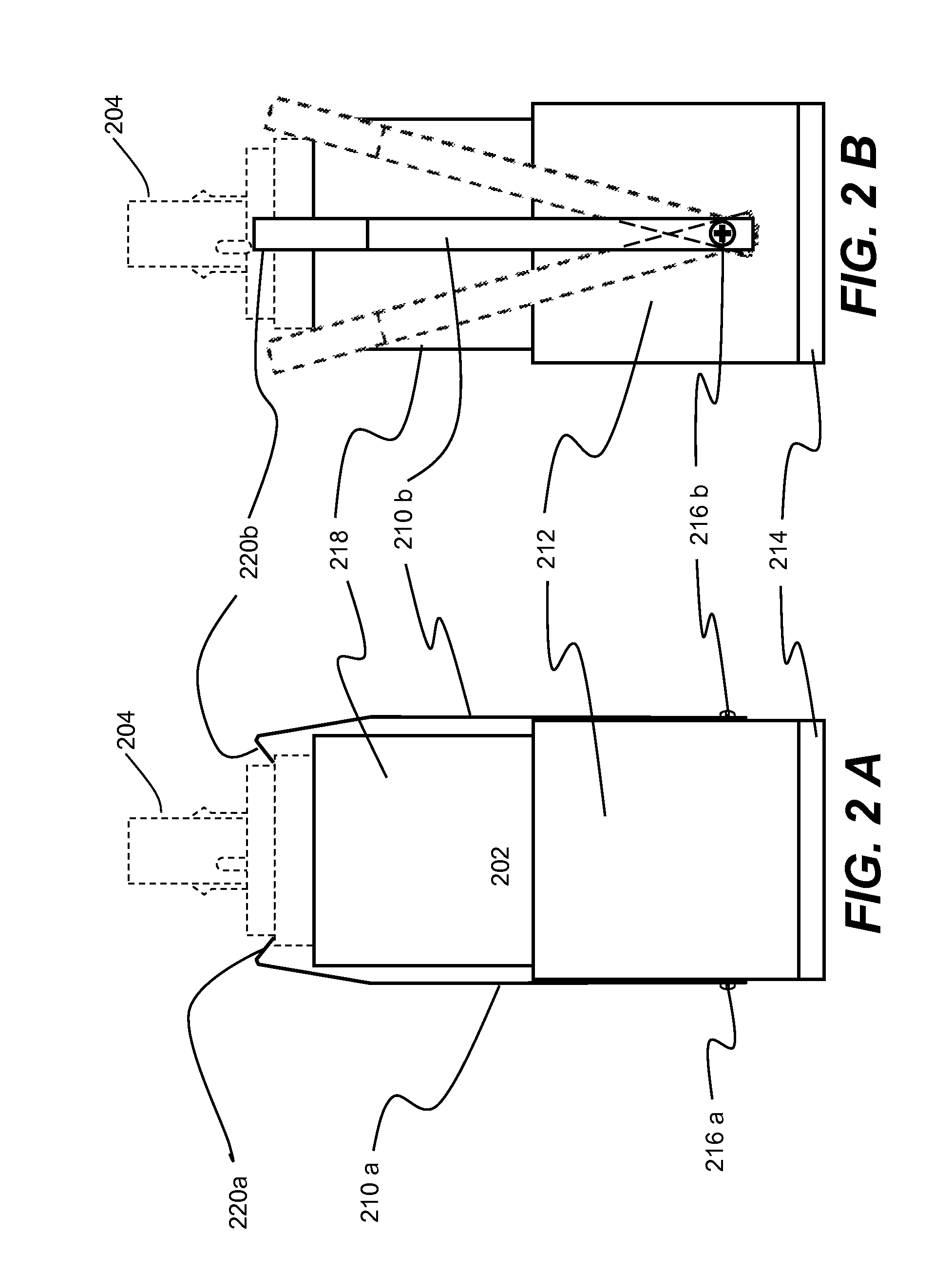
[0013]According to another embodiment, the invention is a device for changing a light bulb, the device comprising: a cylindrical tubular structure having a top opening; and a shaped insert disposed in the cylindrical tubular structure to accommodate the light bulb and cause the light bulb to rotate when the cylindrical tubular structure is caused to rotate.

Problems solved by technology

All these variables increase the complexity of a CFL changer.
Installing or changing CFLs installed in high places is not as simple as changing incandescent light bulbs.
Because of the complex shapes and the variations in their configurations, many CFLs cannot be installed using devices designed for installing regular incandescent light bulbs, such as suction cups, or tools with multiple prongs, or “fingers” for grapping a light bulb.
None of the existing light bulb changing tools is sufficient to perform such a task.

Method used


Image

  • Lamp changers
  • Lamp changers
  • Lamp changers

Examples


Embodiment Construction

[0021]The detailed description of the invention is presented largely in terms of procedures, steps, logic blocks, processing, and other symbolic representations that directly or indirectly resemble the operations of one or more mechanical devices. These process descriptions and representations are typically used by those skilled in the art to most effectively convey the substance of their work to others skilled in the art.

[0022]Numerous specific details are set forth in order to provide a thorough understanding of the present invention. However, it will become obvious to those skilled in the art that the present invention may be practiced without these specific details. In other instances, well known methods, procedures, components, and circuitry have not been described in detail to avoid unnecessarily obscuring aspects of the present invention.

[0023]Reference herein to “one embodiment” or “an embodiment” means that a particular feature, structure, or characteristic described in con...


PUM


Abstract

Devices for changing a light bulb (e.g., a compact fluorescent lamp or CFL), especially for those installed in high places, are disclosed. The device has a cylindrical tubular structure with one end opening to accommodate a light bulb. In one embodiment, at least one flexible thin arm with one end shaped to form a hook is pivotably affixed to the tubular structure. In another embodiment, a shaped insert is disposed in the tubular structure to provide necessary friction force to hold the light bulb in place during the changing process. The present invention is suitable for changing various types of CFLs.

Description

BACKGROUND OF THE INVENTION[0001]1. Field of the Invention[0002]The present invention generally relates to mechanical devices for extracting and installing electrical devices, and more particularly, relates to devices for changing light bulbs.[0003]2. Description of Related Art[0004]As a way of reducing energy consumption, energy efficient compact fluorescent lamps (CFLs) are being widely used to replace the traditional high energy consumption incandescent light bulbs.[0005]A typical CFL is constructed in two parts: a base housing the electronic ballast circuits, and one or more gas-filled, phosphor-coated, sealed glass tube, or compact fluorescent tubes (CFT), connected to the ballast circuit. The base of a CFL is configured to fit into a light fixture outlet. When electricity is introduced, the ballast circuit provides the required electrical conditions to turn on the CFL. In general, CFLs are installed either by screwing into a light fixture or by inserting into a detent socket.[...

Claims


Application Information

Patent Timeline
Patent Type & Authority Patents(United States)
IPC IPC(8): H01K3/32
CPCH01K3/32H01J9/006Y02B20/19Y02B20/00
Inventor BELL, MARK
Owner BELL MARK
Why Eureka
Try Eureka