

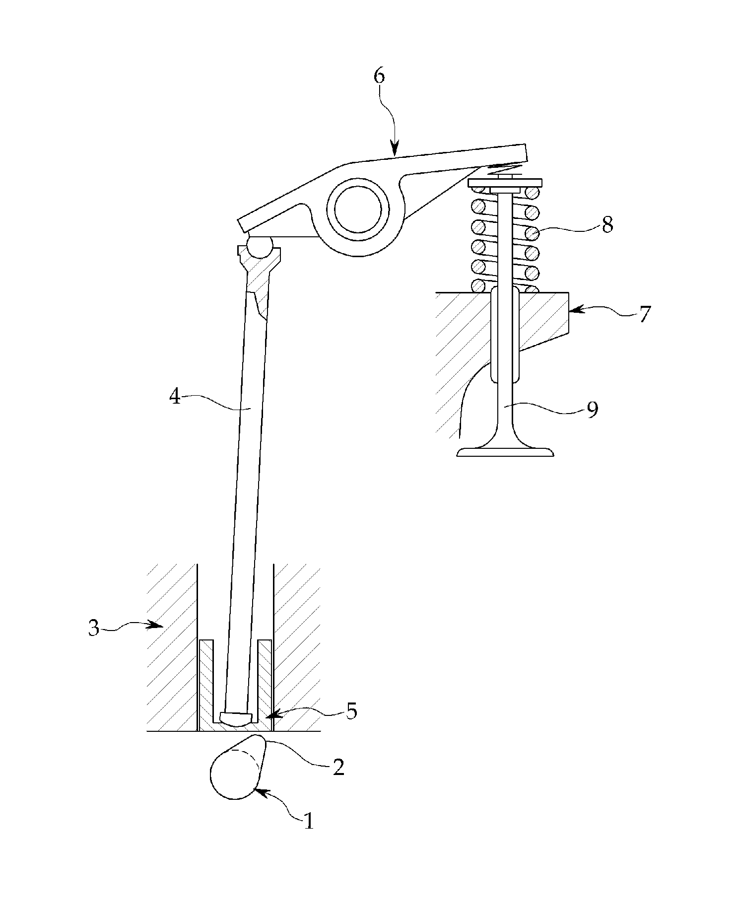
Cam follower with improved structure to increase limit load
a technology of cam follower and limit load, which is applied in the direction of valve arrangement, machines/engines, mechanical equipment, etc., can solve the problems of large amount of heat and wear, two solid surfaces that are not easy to be easily damaged, and poor friction properties, so as to improve the limit load of the cam and the cam follower. , the effect of improving the lubrication sta
- Summary
- Abstract
- Description
- Claims
- Application Information
AI Technical Summary
Benefits of technology
Problems solved by technology
Method used
Image

Examples
embodiment
[0059
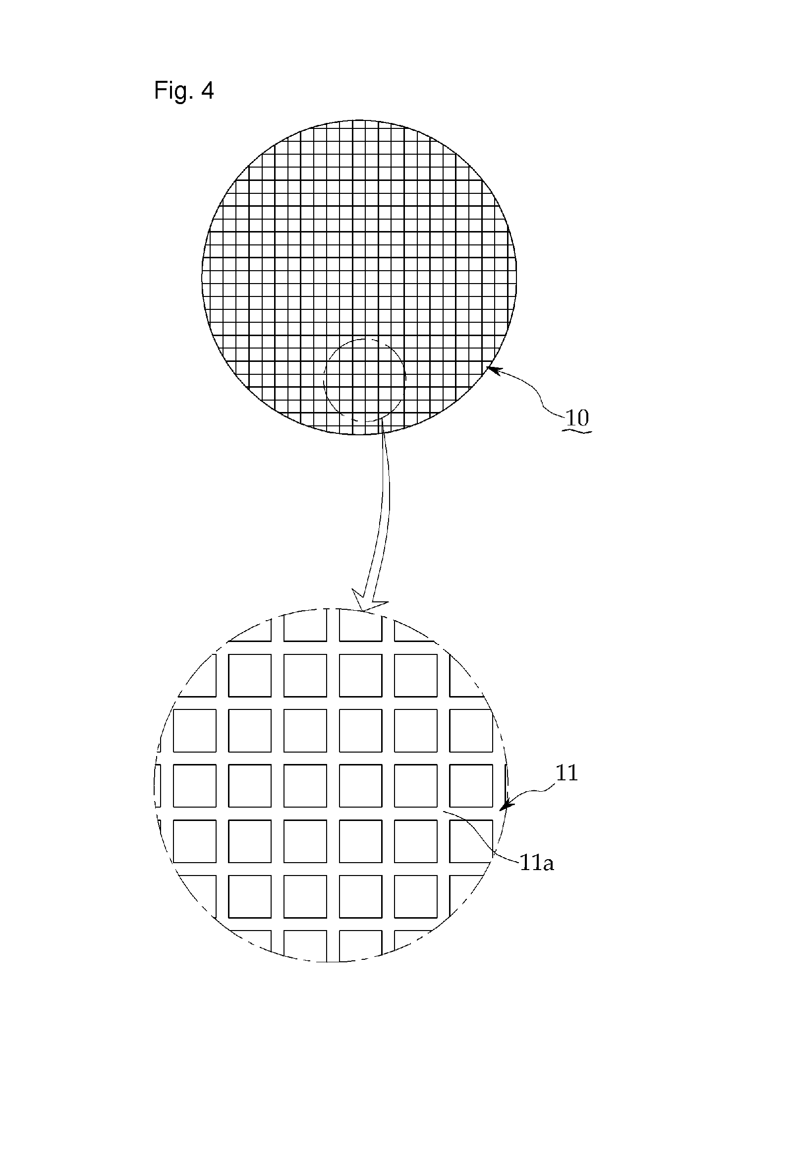
[0060]Next, the excellence of the contact surface 11 having a lattice pattern proposed by the present disclosure is described and a limit load test was performed, as shown in the following table, to optimize the contact surface 11 having a lattice pattern.
[0061]
TABLE 1Design factorTest resultSpecimenWidthDepthGap19.220.823.124.224.625.4Specimen(μm)(μm)(μm)(kgf / mm)(kgf / mm)(kgf / mm)(kgf / mm)(kgf / mm)(kgf / mm)H150101000PassPassPassFail——H2100101000PassPassPassPassFail—H3150101000PassPassPassPassPassFailH450201000PassPassFail———H5100201000PassPassPassFail——H6150201000PassPassPassPassFail—H7100301000PassPassFail———H8100401000PassFail————H9200101000PassPassPassPassFail—H10250101000PassPassFail———H11300101000PassFail————H1215010 500PassPassPassPassFail—H13150102000PassFail————H14150103000PassFail————Comparative———PassFail————Example1
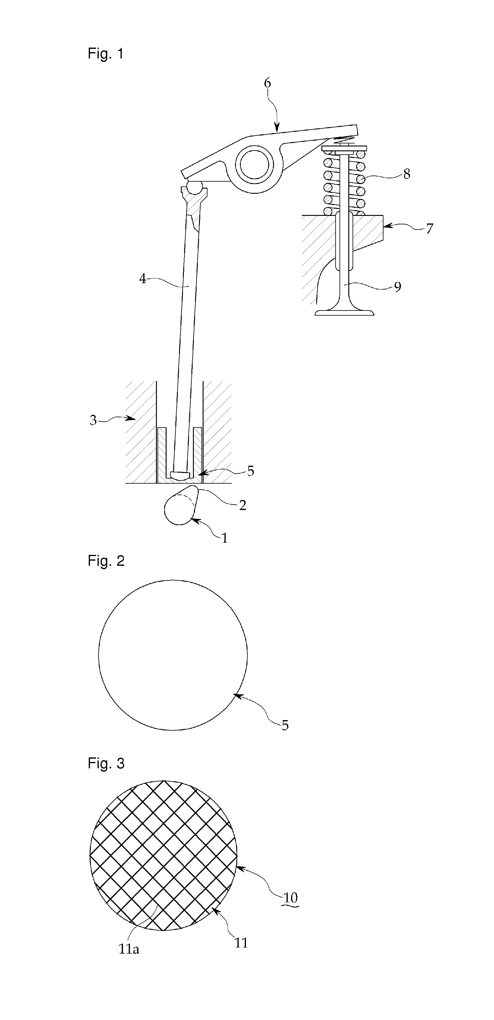
[0062]As shown in FIGS. 3 to 5, the contact surface 11 having a lattice pattern, as described above, is defined by three design variables, that is, the width ...
PUM
 Abstract
Description
Claims
Application Information