Orthopedic plate

a technology of orthopedic plate and bone plate, which is applied in the field of orthopedic plate, can solve the problems of loss of function, early onset of arthritis, and damage to the bones themselves, and achieve the effects of avoiding interference of screws in the bone plate, avoiding fracture, and avoiding fractur

Active Publication Date: 2014-08-19
ORTHOHELIX SURGICAL DESIGNS
View PDF32 Cites 62 Cited by
  • Summary
  • Abstract
  • Description
  • Claims
  • Application Information

AI Technical Summary

Benefits of technology

[0007]In a preferred embodiment, the plate includes a set of tabs or “ears” which are offset from the longitudinal axis of the plate, and further which allow the placement of screw holes that are offset from the longitudinal axis of the plate, as well as being offset longitudinally from each other. This allows the plate to be contoured about the circumference of the bone, and for the screws to be positioned at a convergent angle to provide for better pullout values, i.e. such that it requires a greater force to pull the screws from the bone. The ears may be located at the terminal portion of the plate or somewhat more intermediate to the terminus of the plate, depending on the intended application. The plate may also include an intermediate set of ears that similarly have a pair of offset intermediate threaded screw holes that are both longitudinally and laterally, or radially offset from the longitudinal axis of the plate, and which accept screws so as to have their axes at convergent angles. Again, the feature provides for better pullout values, and helps to avoid interference of the screws in the bone. In this instance, the plate includes a central screw hole which is located between the proximal pair of ears, and the intermediate pair of ears. This screw hole is preferably positioned so that the axis forms a right angle relative to the longitudinal axis of the plate, and further relative to a lateral axis through the hole. Thus, a point in the center of the central screw hole can be used to define the origin of the plate, and the angles of the screw and / or pegs holes can be referenced with X, Y, and Z coordinates relative to this central hole. Further, the topography of the head can be defined using this coordinate system, which permits the manufacture of the plate using computer generated imaging.
[0008]Distal to the intermediate pair of ears, the plate includes a slot which is radiused at either end to accept a screw having a head of the same dimensions as the threaded screw holes. The slot is elongated along the longitudinal axis of the plate. This allows the plate to be loosely attached by inserting a screw through the slot, and prior to tightening the plate can be slid in the longitudinal direction to allow the plate to be optimally positioned on the bone. The slot also allows the bone to be viewed through the plate preferably in the vicinity of the fracture.

Problems solved by technology

Attendant with this relative freedom, the joint itself is somewhat unstable, and easily subjected to trauma resulting in displacement or distortion within the bones of the joint, and in harm to the bones themselves.
While the past conventional wisdom has included a belief that such injuries will tend to heal sufficiently on their own, there is often a loss of function and an early onset of arthritis that can be precipitated by the misdiagnosis and improper treatment of such injuries.
Casting alone, presents the possibility of misalignment of the fragments which can lead to severe loss of function and early onset of arthritis, if the fracture is not properly reduced, and / or if the fragments do not stay in a reduced state, in particular where the patient is not compliant.
External fixators have been demonstrated to have an efficacy, but are cumbersome, cosmetically unappealing, and can lead to the possibility of infection at the attachment sites.
One issue presented by the use of wires is that a construct is time-consuming to construct; and screws alone, often do not provide the stability required for fusion of the fragments.
Plates have the benefit of providing a construct that is designed for ease of implantation, and at the same time have the disadvantage that there is a significant variety in the shape and size of individual bones.

Method used


Image

  • Orthopedic plate
  • Orthopedic plate
  • Orthopedic plate

Examples


Embodiment Construction

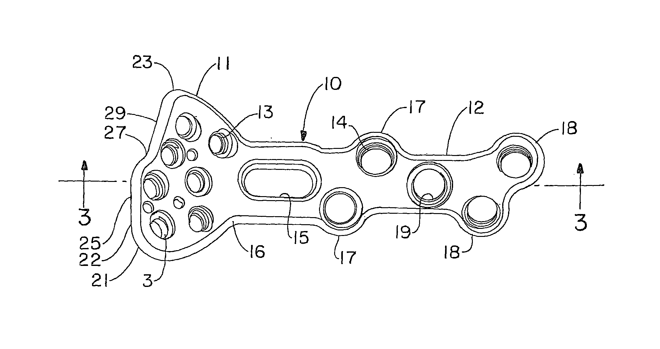
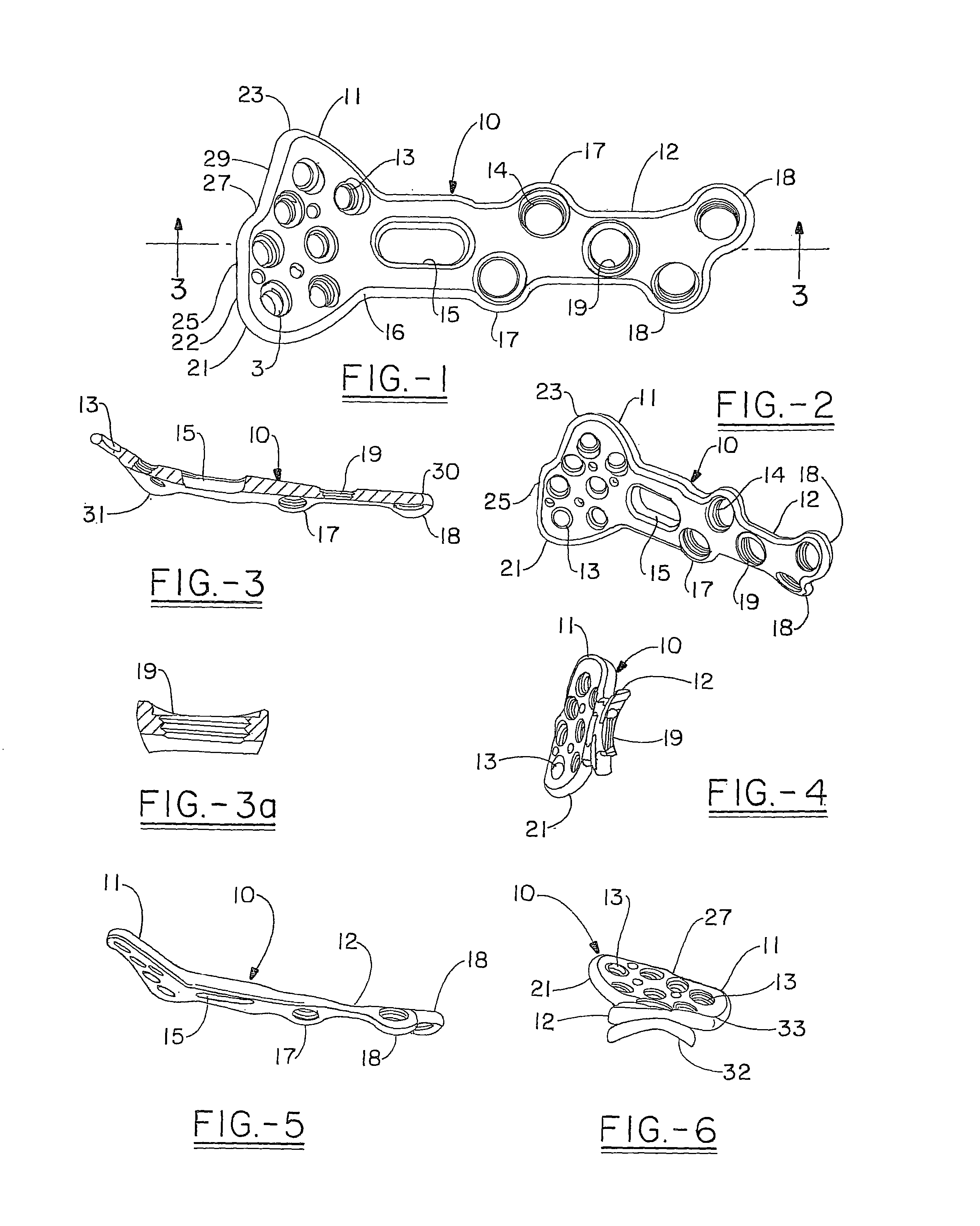
[0056]The present invention relates to an orthopedic plate that can be used to stabilize the fracture of bone such as a radial bone, and in particular to the longitudinally extending plate portion, which tends to be placed proximally to the head, in the event that there is one.

[0057]A first embodiment of the plate is shown generally at 10 in FIG. 1 which includes a first, most distal portion or head 11 which has a profile from the top view similar to the palm of a hand, or which is shaped like a truncated heart, or a modified kidney shape. The head 11 slopes upward in a complex and organic topography away from the more elongated inversely curving proximal portion 12 of the plate. The head 11 includes a plurality of holes 13 for pegs, which holes can be internally threaded or not, or can also include means to provide for a variable locking axis. The proximal plate portion 12 also includes a plurality of holes 14 for screws, which similarly can include internal threads, or which can b...


PUM


Abstract

An orthopedic plate has a portion with a curved bottom surface that is designed to extend longitudinally along the bone and change the inferior curve as it advances proximally along the bone from a shallower to a sharper radius and further spirals downward as the plate advances. The plate includes a set of tabs, offset from the longitudinal axis of the plate to provide for better pullout values. The ears may be located at the terminal portion of the plate or somewhat more intermediate to the terminus of the plate, depending on the intended application. A point in the center of the central screw hole can be used to define the origin of the plate, and the angles of the screw and / or pegs holes can be referenced with Z, Y, and Z coordinates relative to this central hole.

Description

[0001]This application is based on U.S. Provisional Application Ser. No. 60 / 780,027 filed on Mar. 7, 2006FIELD OF THE INVENTION[0002]The present invention relates to an orthopedic plate for fixation of bones. In particular it relates to a terminal section of an orthopedic plate that is useful for stabilization of small bones; for example, for a tibial plate for fixation of a tibial fracture, or for a distal radial plate for fixation of a distal radial fracture, or other fracture areas that can benefit from the design of the present invention.BACKGROUND OF THE INVENTION[0003]The ankle joint involves the intersection of the tibia, the fibula and the tarsals and metatarsals. The wrist is the joint formed at the intersection of the radius, the ulna, the carpals and the metacarpals. Both of these joints are designed to allow a great deal of freedom in the movement of the relevant appendage (i.e. the hand or foot). Attendant with this relative freedom, the joint itself is somewhat unstabl...

Claims


Application Information

Patent Timeline
Patent Type & Authority Patents(United States)
IPC IPC(8): A61B17/80
CPCA61B17/8047A61B17/8061A61B17/8605A61B2017/1782A61B17/8057A61B17/1728A61B17/80A61B17/8052A61B17/1782
Inventor STRNAD, LEE A.KAY, DAVID B.MARTIN, AMANDAWYNKOOP, G. MARTIN
Owner ORTHOHELIX SURGICAL DESIGNS
Why Eureka
Try Eureka