
Data load redistribution within a relay enhanced telecommunication network

a telecommunication network and data load technology, applied in the field of mobile wireless telecommunication networks, can solve the problems of air interface data load and strong influence, and achieve the effect of enhancing path loss and enhancing radio quality

Inactive Publication Date: 2014-08-19
WSOU INVESTMENTS LLC
View PDF1 Cites 24 Cited by
  • Summary
  • Abstract
  • Description
  • Claims
  • Application Information

AI Technical Summary

Benefits of technology

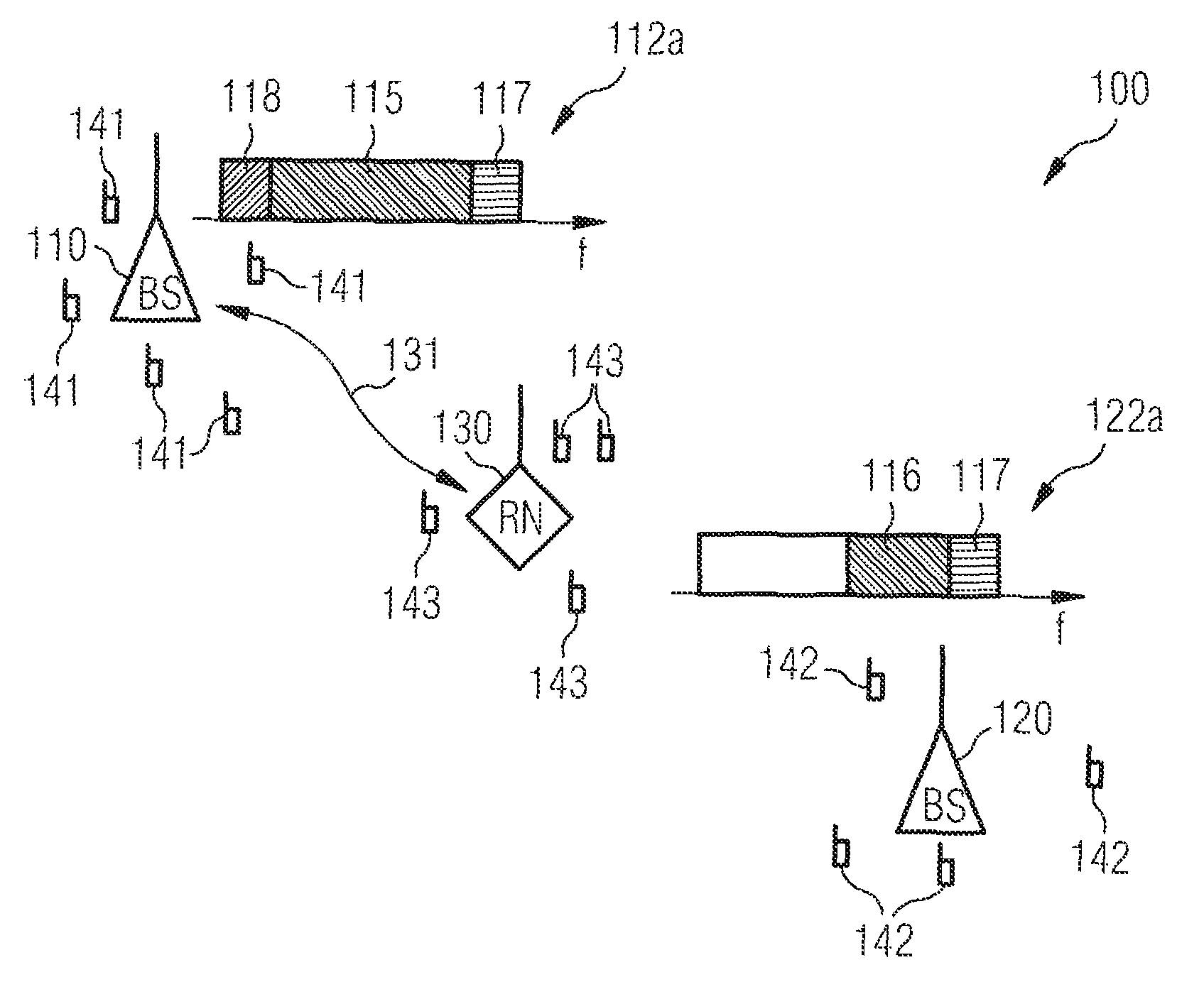
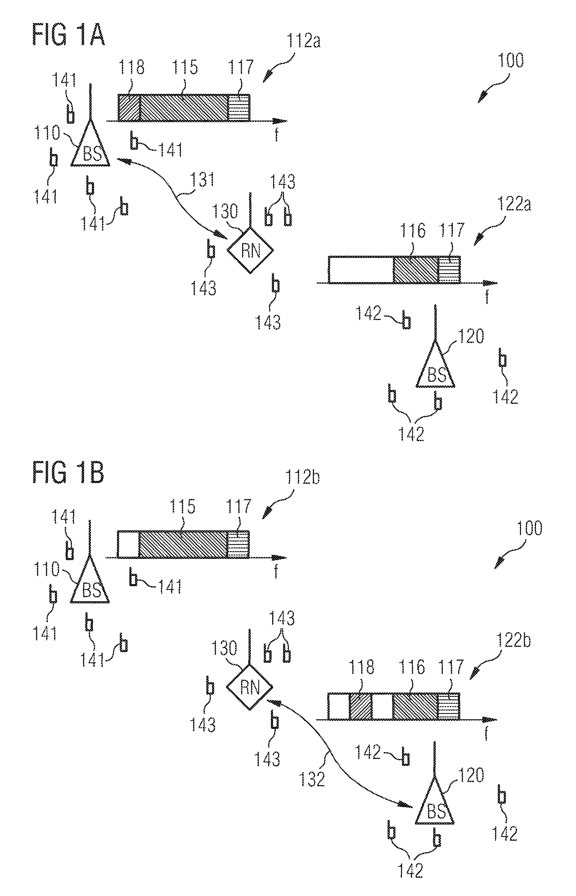
[0011]It is mentioned that apart from considering the data load with respect to the different base stations one can also consider the data load on the available air interfaces within a first cell being assigned to the first base station and a second cell being assigned to the second base station. Thereby, the first cell and the second cell refer to spatial regions, in which user equipments are predominately served by the first base station and the second base station, respectively. In this context, if one assumes no movement of the user equipments, the described reallocation does not have any effect on the air interface data load, which is caused by the communication between the user equipments and the relay node. However, by contrast thereto, the air interface data load, which is caused by the backhaul traffic data between the relay node and the corresponding base station, will be strongly affected by the reallocation procedure. As a consequence, by carrying out the described data load redistribution method not only the device-related data load on the base stations but also the overall data load on the air interfaces within the cells of the telecommunication will be redistributed. Thereby, interference effects between different radio links may be reduced significantly.
[0041]In this respect it is mentioned that both relay nodes and base stations can easily contribute to such a gain, because beam forming is easier for network elements which do not move within the telecommunication network.

Problems solved by technology

However, by contrast thereto, the air interface data load, which is caused by the backhaul traffic data between the relay node and the corresponding base station, will be strongly affected by the reallocation procedure.

Method used


Image

  • Data load redistribution within a relay enhanced telecommunication network
  • Data load redistribution within a relay enhanced telecommunication network

Examples


Embodiment Construction

[0055]The illustration in the drawing is schematically. It is noted that in different figures, similar or identical elements are provided with the same reference signs or with reference signs, which are different from the corresponding reference signs only within the first digit. In the first operational state

[0056]FIG. 1a shows a relay enhanced telecommunication network 100 in a first operational state. The telecommunication network 100 comprises a first base station 110, which spans a first cell of the telecommunication network 100, a second base station 120, which spans a second cell of the telecommunication network 100 and a relay node 130. The telecommunication network 100 further comprises a plurality of user equipments 141, 142 and 143. The user equipments 141 are served directly by the first base station 110. The user equipments 142 are served directly by the second base station 120. The user equipments 143 are connected to the relay node 130.

[0057]In the first operational s...


PUM


Abstract

It is described a method for changing the data load distribution within a telecommunication network including a first base station, a second base station and a relay node being connected to the first base station and / or to the second base station. The described method includes (a) establishing for each of a plurality of user equipments a first indirect connection to the first base station via the relay node, (b) establishing in a collective manner for each of the plurality of user equipments a second indirect connection to the second base station via the relay node, and (c) terminating in a collective manner for each of the plurality of user equipments the first indirect connection. It is further described a network element, which is adapted to carry out the above described data load redistribution method, and a computer program, which is adapted for controlling the above described data load redistribution method.

Description

FIELD OF INVENTION[0001]The present invention generally relates to the field of mobile wireless telecommunication networks, such as for instance 3GPP Long Term Evolution (LTE) and Advanced LTE (LTE-A) networks. The present invention is further related to a system behavior in mobile telecommunication networks with relay nodes, which may support an automatic network configuration for instance by a so called Self Optimizing Network (SON) procedure, which is of major concern in future mobile wireless telecommunication networks. Specifically, the present invention relates to method for changing the data load distribution within a telecommunication network comprising a first base station, a second base station and a relay node being connected to the first base station and / or to the second base station. Further, the present invention relates to a network element, which is adapted to carry out the above described data load redistribution method. Furthermore, the present invention relates to...

Claims


Application Information

Patent Timeline
Patent Type & Authority Patents(United States)
IPC IPC(8): H04B3/36H04B7/14
CPCH04W28/08H04B7/2606H04W36/22H04W84/047
Inventor DOTTLING, MARTINFAERBER, MICHAELLACHOWSKI, JAROSLAWLOBINGER, ANDREASMICHEL, JUERGENWALDHAUSER, RICHARD
Owner WSOU INVESTMENTS LLC
Learn More