High efficiency, ternary mix engine

a mix engine, high efficiency technology, applied in the direction of machines/engines, mechanical equipment, non-fuel substance addition to fuel, etc., can solve the problems of increasing the cost of fuel consumption, so as to maximize the heat available for generating steam, prevent damage from freezing, and save heat

Active Publication Date: 2014-08-26
GRANNELL SHAWN +1
View PDF34 Cites 0 Cited by
  • Summary
  • Abstract
  • Description
  • Claims
  • Application Information

AI Technical Summary

Benefits of technology

[0032]The additional convective heat loss becomes much larger, and the efficiency of the engine suffers accordingly, if a large portion of any gas is admitted into the working chamber after a substantial portion of the fuel is combusted, because the working fluid is relatively much hotter than the working chamber boundaries, after a substantial portion of the fuel is combusted. The additional convective heat loss from the working fluid, due to admission of steam, fuel, or oxidizer, is minimized when all entire portions of steam, fuel, and oxidizer are admitted into the working chamber before ignition of the fuel.
[0063]The steam generator may be stored empty while the engine is not operating, thereby preventing damage from freezing. Otherwise, the steam generator may store liquid or frozen water in one or more “V” shaped troughs, thereby maintaining the availability of water for the next start. All pumps or other damage prone areas may be drained or purged with air or steam at shutdown, thereby preventing damage from freezing. The engine may revert to firing without steam admission at startup until enough heat and water accumulate, such that the steam generator becomes operational.

Problems solved by technology

The additional convective heat loss becomes much larger, and the efficiency of the engine suffers accordingly, if a large portion of any gas is admitted into the working chamber after a substantial portion of the fuel is combusted, because the working fluid is relatively much hotter than the working chamber boundaries, after a substantial portion of the fuel is combusted.
If the fuel were to be ignited by contacting of the fuel by the steam, then an early portion of the steam would ignite the fuel before the remaining late portion of the steam could be admitted into the working chamber, thereby incurring an excessive additional convective heat loss upon admission of the remaining late portion of the steam.

Method used


Image

  • High efficiency, ternary mix engine
  • High efficiency, ternary mix engine
  • High efficiency, ternary mix engine

Examples


Embodiment Construction

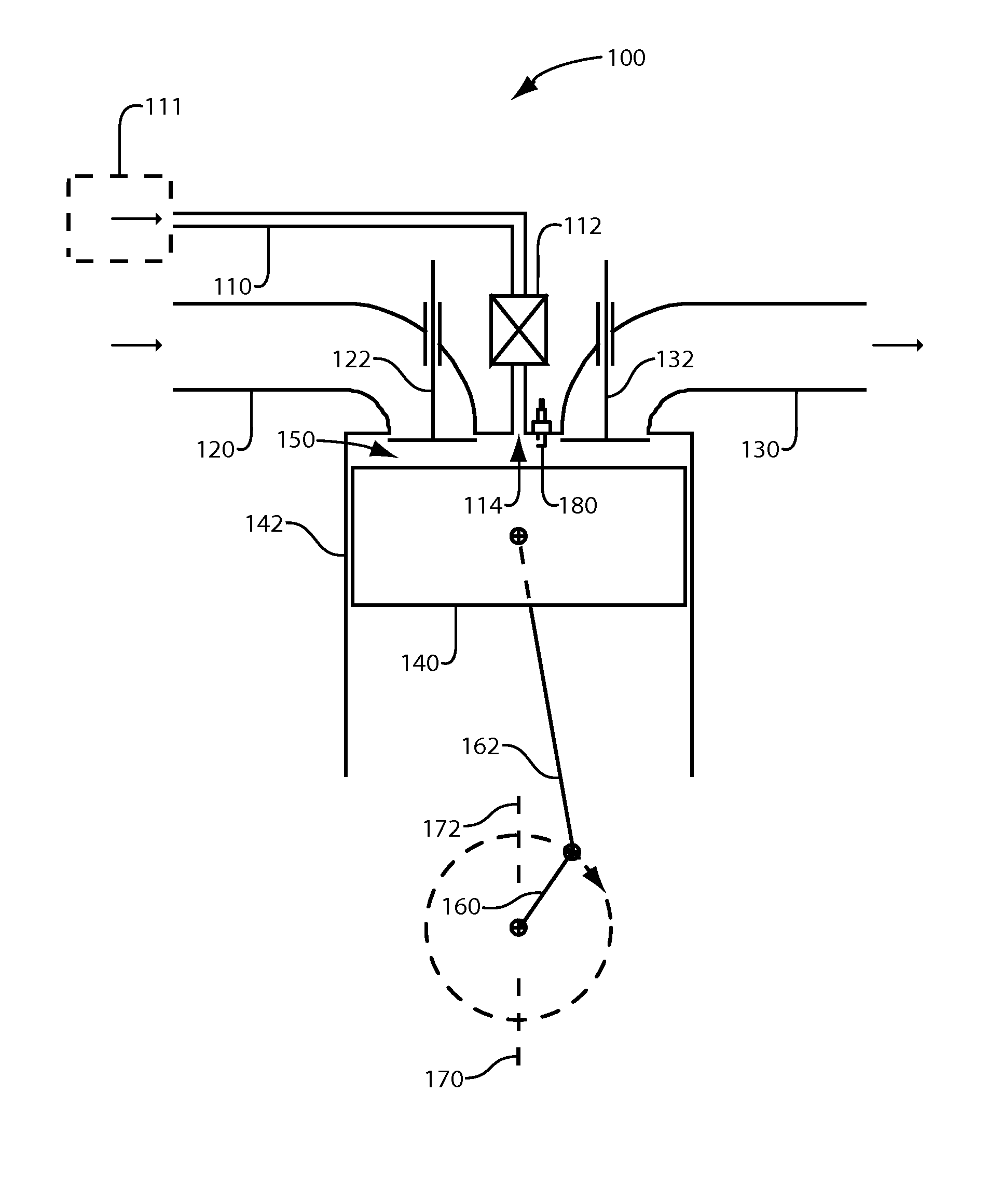
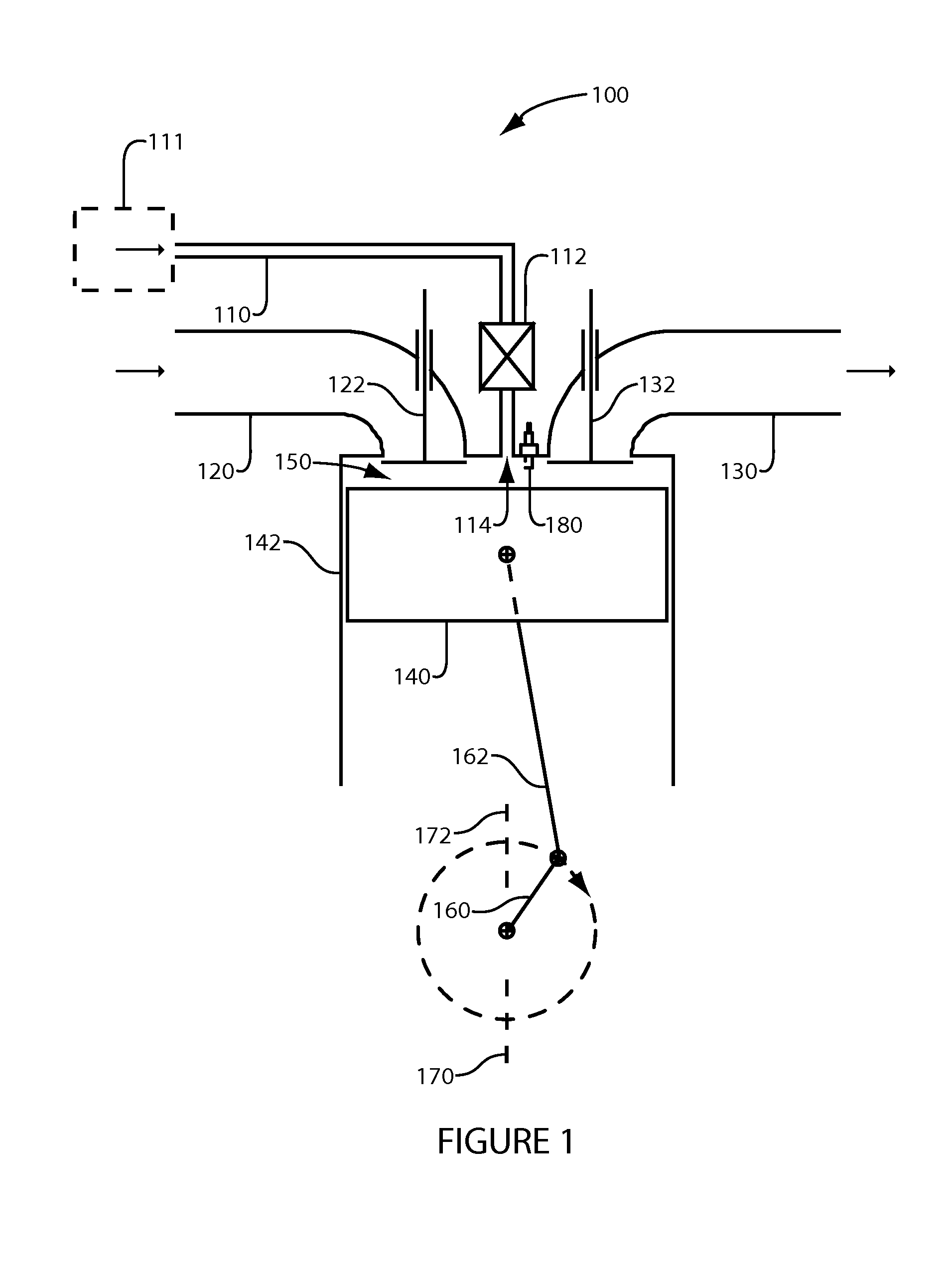
[0074]FIG. 1 illustrates a representative embodiment of the Ternary Mix Engine. The engine 100 has a working chamber 150 and an igniter 180. The working chamber 150 comprises a cylinder 142, which serves as a fixed boundary, and a piston 140, which serves as a movable boundary for performing compression and expansion of a working fluid. The piston 140 is coupled to a rotating crankshaft 160 by a connecting rod 162 in a conventional manner. In this particular example, bottom center corresponds to a crankshaft position 170, and the end of expansion also happens to correspond to crankshaft position 170. Top center corresponds to a crankshaft position 172, and for 4-cycle operation, the end of exhaust / beginning of intake also happens to correspond to crankshaft position 172. However, for a different engine type, such as a rotary engine, bottom center and the end of expansion may be different working chamber positions, bottom center referring herein to the beginning of compression.

[0075]...


PUM


Abstract

Pressurized and superheated, dry steam is admitted into the working chamber of a spark ignition engine for the purpose of increasing the thermal efficiency of the engine. The steam is admitted into the working chamber near the end of compression, and before ignition of the fuel. An igniter ignites the fuel. Additional work is pneumatically recovered from the steam, thus augmenting the total work obtained by the engine.

Description

REFERENCE TO RELATED APPLICATIONS[0001]This application is a continuation-in-part of U.S. patent application Ser. No. 13 / 769,497, filed Feb. 18, 2013, which is incorporated herein by reference.FIELD OF THE INVENTION[0002]The present invention relates generally to internal combustion engines admitting steam into the working chamber for the purpose of increasing the efficiency of the engine, and more particularly, to the invention disclosed herein, referred to as a “Ternary Mix Engine”, wherein a ternary mixture comprising fuel, oxidizer, and steam is formed under compression. The ternary mixture is combusted upon ignition of the fuel by an igniter. The steam augments the work obtained by the engine.BACKGROUND OF THE INVENTION[0003]Due to rising fuel prices and concerns about future fuel availability, many have sought to increase the efficiency of engines. Desirably, by increasing engine efficiency, less fuel is consumed, and the cost of fueling internal combustion engines is decrease...

Claims


Application Information

Patent Timeline
Patent Type & Authority Patents(United States)
IPC IPC(8): F02B47/02F02M25/038
CPCF02M25/038Y02T10/121Y02T10/12
Inventor GRANNELL, SHAWNGILLESPIE, DONALD E.
Owner GRANNELL SHAWN
Why Eureka
Try Eureka