
Diesel engine efficiency improvement

a technology of diesel engine and efficiency improvement, applied in the direction of machines/engines, mechanical equipment, hydrocarbon oil treatment products, etc., can solve the problems of reducing fuel efficiency, requiring periodic online re-generation, and unburned hydrocarbons, so as to improve the efficiency of the engine and increase the engine efficiency. the effect of 1%

Inactive Publication Date: 2013-12-19
SASOL TEKHNOLODZHI PROPRIEHJTEHRI LTD
View PDF12 Cites 0 Cited by
  • Summary
  • Abstract
  • Description
  • Claims
  • Application Information

AI Technical Summary

Benefits of technology

This patent describes the use of a special type of fuel called distillate fuel, which has a low density and is made from a process called distillation. This fuel is designed to improve engine efficiency when running a diesel engine under low oxygen conditions. By using this fuel, the engine can achieve better performance compared to traditional crude-derived diesel fuel. This patent also includes a method for operating the engine using the special fuel.

Problems solved by technology

By contrast, rich diesel combustion typically results in reduced fuel efficiency and dramatically increased soot, unburned hydrocarbon, and CO emissions due to incomplete combustion of the diesel fuel.
Facilitating stoichiometric or fuel-rich diesel engine operation has become a critical issue in responding to legislation evolution focussed on NOx emission reduction.
This device, however, requires periodic online re-generation through exposure to exhaust reductants under very low oxygen conditions.
This is obviously not easily achieved where the exhaust stream is oxygen-rich—as is the case for conventional fuel-lean diesel engine operation.
Additionally, diesel engines operating with significant EGR (exhaust gas recycling) in order to reduce NOx emissions, may also experience a reduction in fuel efficiency and increase in soot or particulate formation caused by incomplete fuel combustion.
The smaller engine displacement means that in such engines, air availability may constrain maximum power output.

Method used


Image

  • Diesel engine efficiency improvement
  • Diesel engine efficiency improvement
  • Diesel engine efficiency improvement

Examples


example

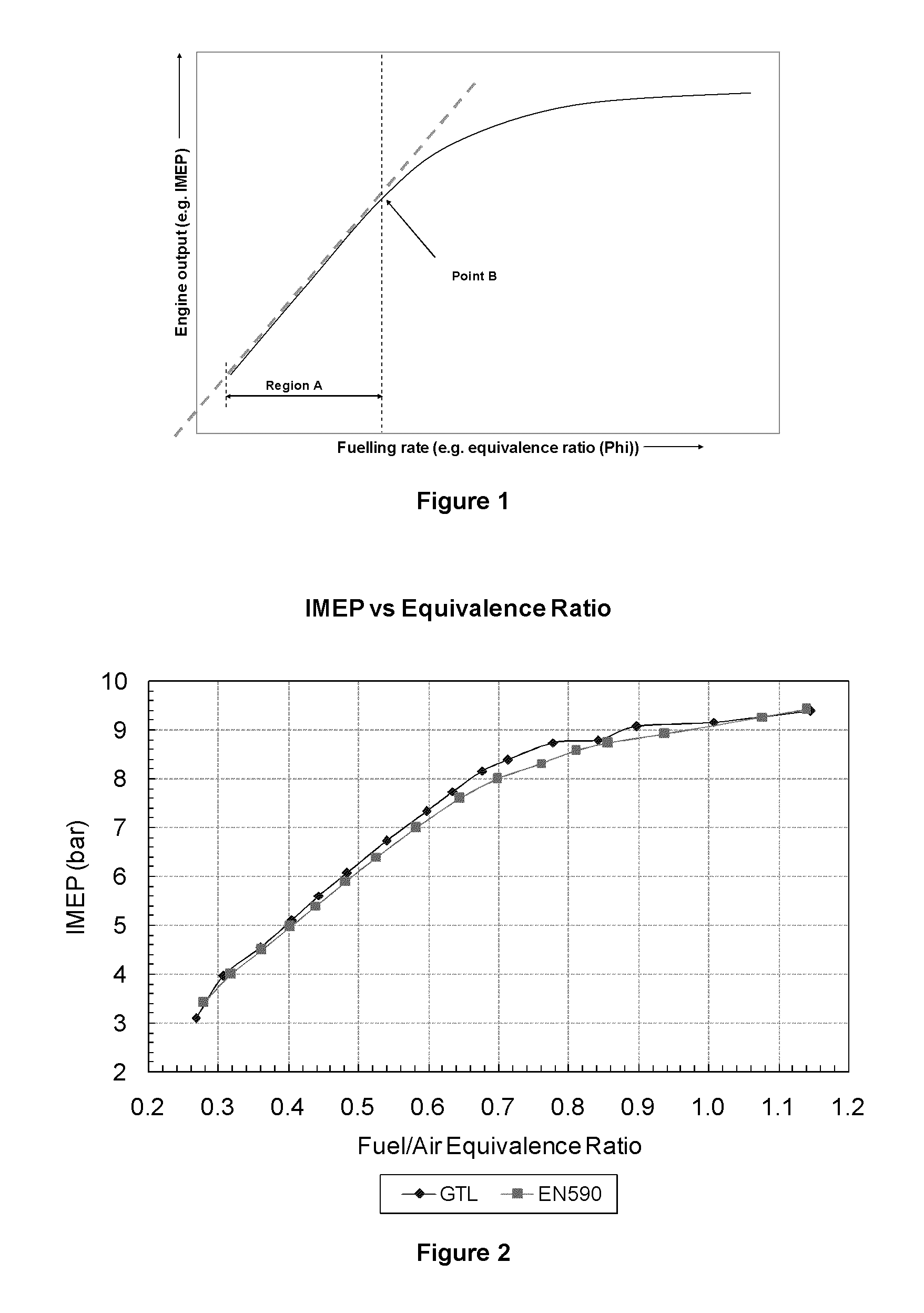
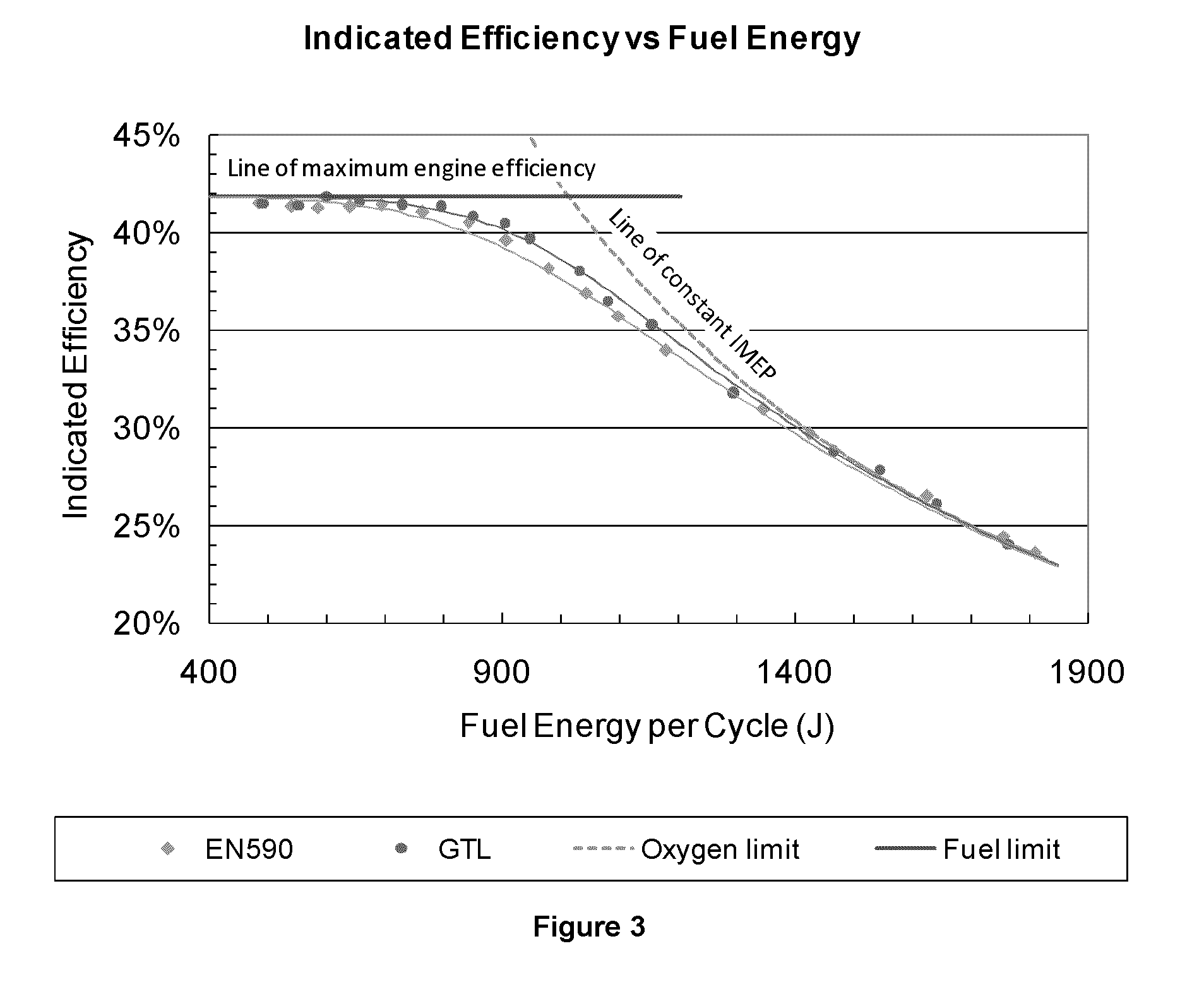
[0050]Engine testing was carried out over a range of air / fuel conditions using two test fuels:[0051]GTL, a fully-synthetic FT-derived diesel; and[0052]EN590, a representative crude-derived reference European diesel.

TABLE 1Properties of test fuelsCrude-derived dieselFT dieselFuel propertyUnitEN590GTLDensity @ 20° C.g · cm−60.82970.7647Flashpoint° C.6063Viscosity @ 40° C.cSt2.732.46CFPP° C.−8−5Sulphur contentppmCetane number54.8>74Carbon contentMass %86.285.0Hydrogen contentMass %13.815.0Total aromatic contentMass %27.90.14Lower heating valueMJ / kg42.7543.81

[0053]Engine testing was conducted on a Ricardo Hydra single cylinder research engine which was configured to resemble a modern passenger car diesel engine.

TABLE 2Hydra engine specificationsEngine parameterUnitValueBoremm80.26Strokemm88.90Swept volumecm3450Compression ratio16:1Fuel injection systemCommon rail - DI

[0054]The test procedure involved running the engine under stable conditions and gradually increasing the injection durat...


PUM


Abstract

The invention provides a method of operating a diesel engine under oxygen-limited conditions such that the efficiency of the engine is at least 1% improved over the engine efficiency obtained when using a conventional crude-derived diesel fuel, said method including the combustion of a distillate fuel having a density of below 0.800 g.cm−3 in the engine. The invention extends to the use of a distillate fuel with a density less than 0.800 g.cm−3 (at 20° C.) for achieving increased engine efficiency when operating a diesel engine under oxygen-limited conditions, said use including combusting said fuel such that the efficiency of the engine is at least 1% improved over the engine efficiency obtained when using a conventional crude-derived diesel fuel.

Description

FIELD OF THE INVENTION[0001]The present invention relates to suitable fuel compositions or fuel properties for diesel engines operating under oxygen-limited conditions.BACKGROUND OF THE INVENTION[0002]Historically diesel engines operate at fuel-lean conditions—where fuel combustion occurs in an environment with oxidiser / air present in excess quantities to that required for stoichiometric combustion. This allows for more complete and hence efficient combustion of the diesel fuel; and partially accounts for the exceptional fuel economy of diesel engines. By contrast, rich diesel combustion typically results in reduced fuel efficiency and dramatically increased soot, unburned hydrocarbon, and CO emissions due to incomplete combustion of the diesel fuel.[0003]Operation of diesel engines at air / fuel ratios significantly removed from the fuel-lean combustion efficiency optimum is however becoming far more prevalent for multiple reasons.[0004]Facilitating stoichiometric or fuel-rich diesel...

Claims


Application Information

Patent Timeline
Patent Type & Authority Applications(United States)
IPC IPC(8): F02B75/12
CPCF02B75/12C10G2/00C10L1/08F02D19/081F02B3/06F02D19/0649C10G2300/1022C10G2300/308C10G2400/04Y02T10/30
Inventor VELAERS, ADRIAN JAMESSCHABERG, PAUL WERNERYATES, ANDREW
Owner SASOL TEKHNOLODZHI PROPRIEHJTEHRI LTD
Learn More