

Vehicle seat
a seat and vehicle technology, applied in the field of vehicle seats, can solve the problems of not being able and not being able to keep, so as to reduce the load applied to the neck of the occupant, reduce the angle difference, and reduce the load
- Summary
- Abstract
- Description
- Claims
- Application Information
AI Technical Summary
Benefits of technology
Problems solved by technology
Method used
Image

Examples
Embodiment Construction
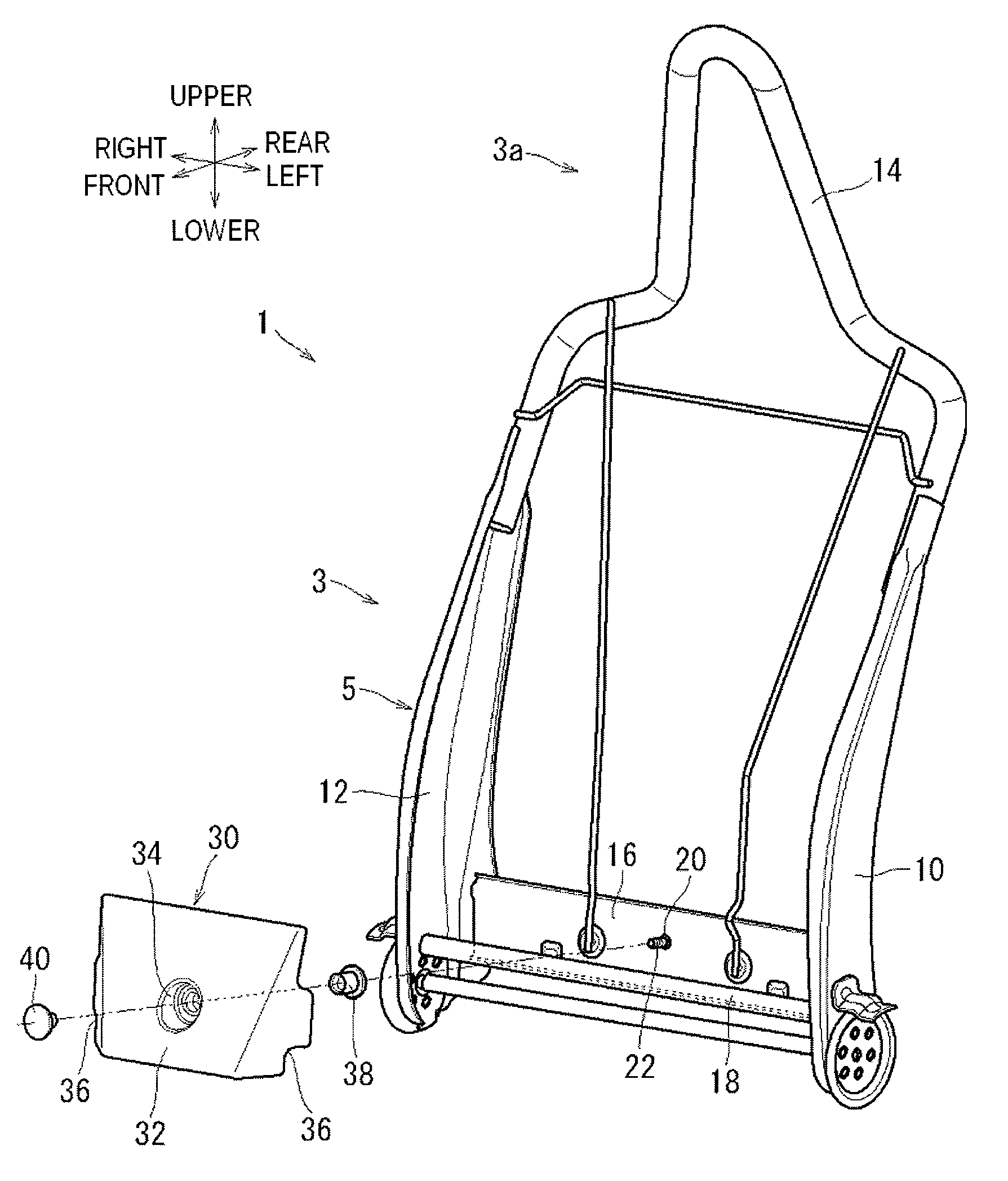
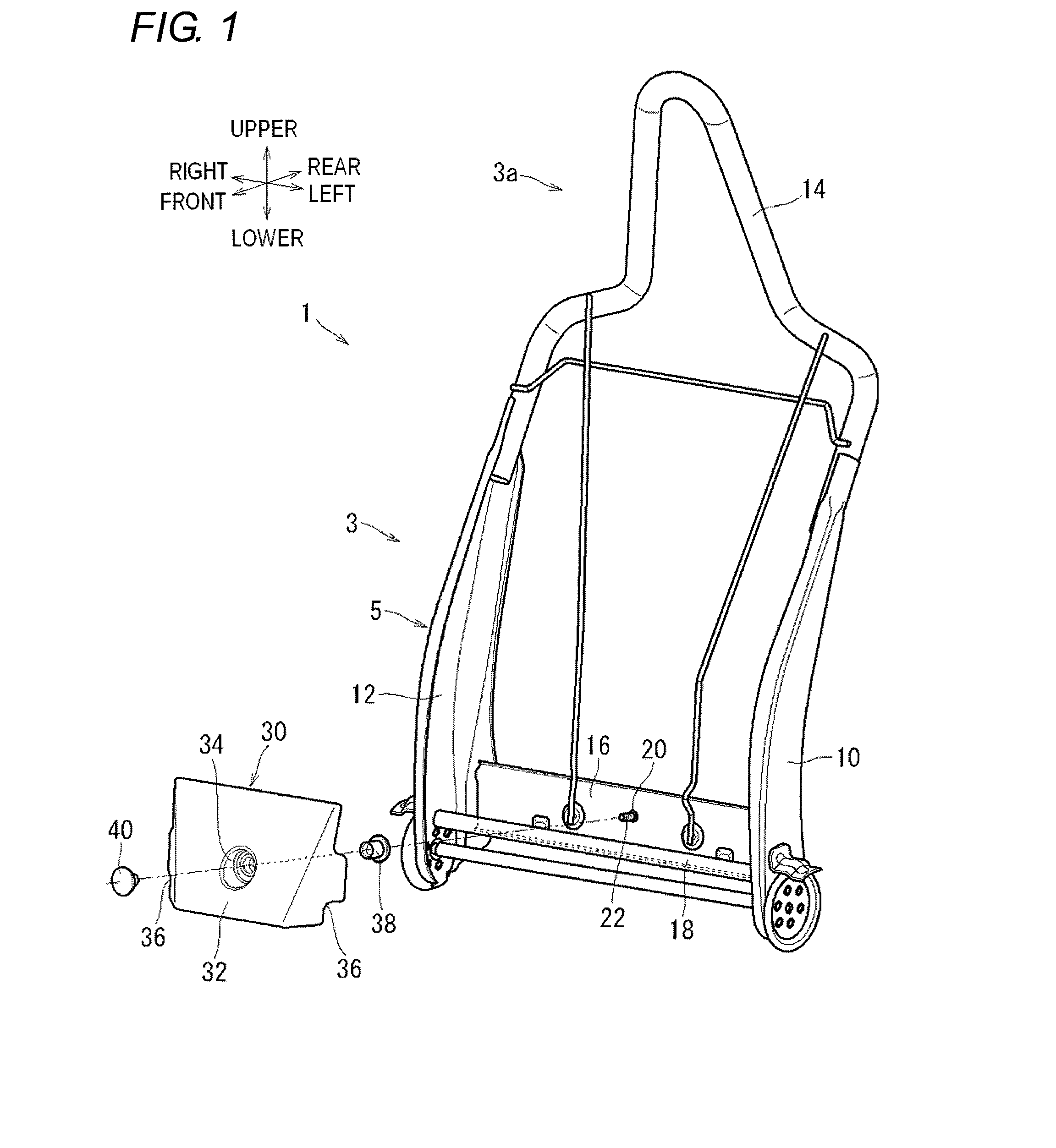
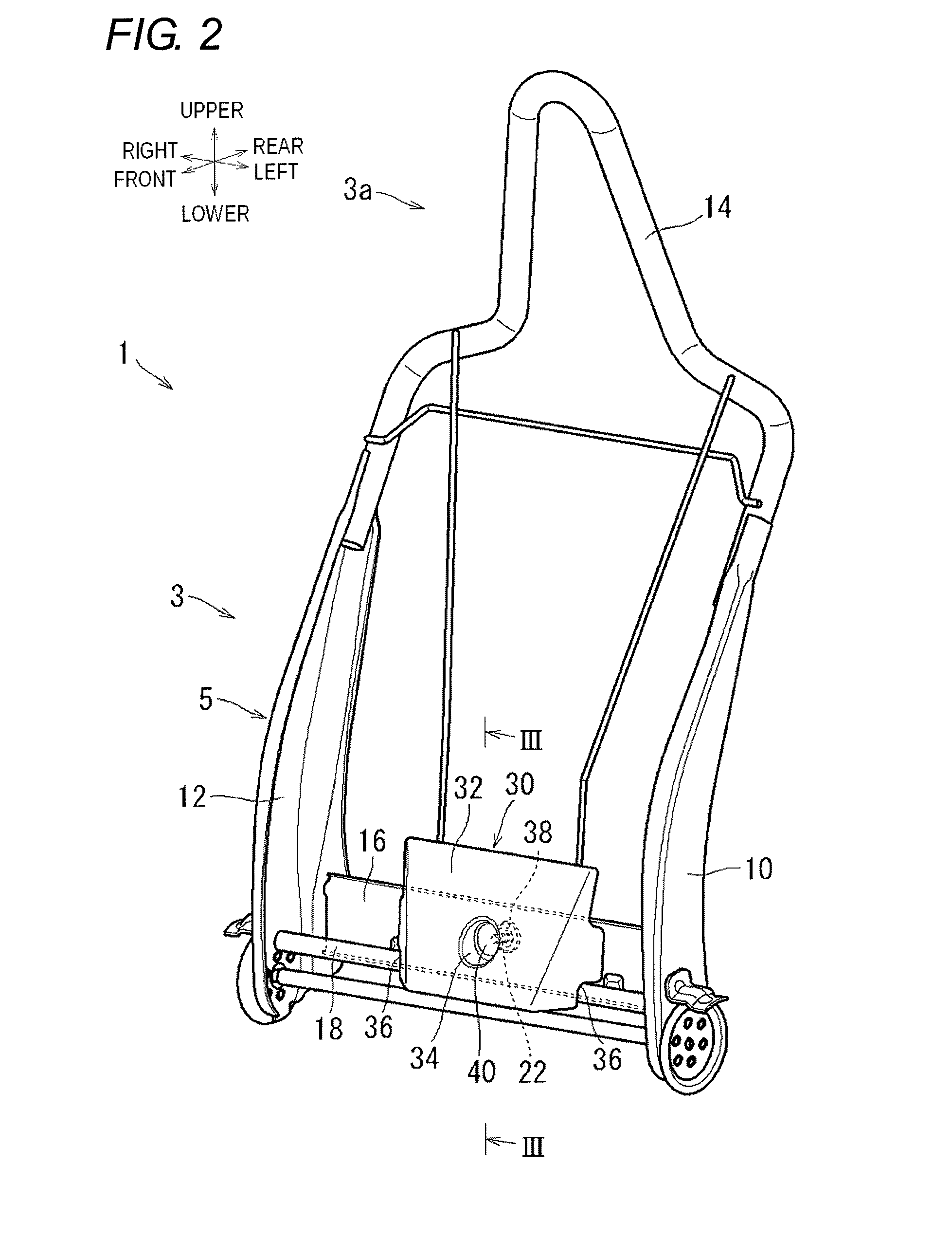
[0017]Illustrative embodiments of the present invention will be described with reference to FIGS. 1 to 4. In the below descriptions, a front seat 1 is an example of a vehicle seat. In the descriptions, the upper, lower, front, rear, left and right respectively indicate the upper, lower, front, rear, left and right directions shown in the drawings, i.e., the upper, lower, front, rear, left and right directions based on the front seat 1.
[0018]A schematic configuration of the front seat1 will be described with reference to FIGS. 1 to 3. The front seat 1 includes a seat cushion (not shown) and a seatback 3 having a headrest 3a. The configuration of the seatback 3 will be described in detail. In FIGS. 1 to 3, a pad configuration and a cover configuration of the seatback 3 are omitted so as to easily appreciate an internal structure of the seatback 3.
[0019]The seatback 3 includes a back frame 5, a covering pad (not shown) that is assembled to the back frame 5 while enclosing the back fram...
PUM
 Abstract
Description
Claims
Application Information