In-band signaling in optical cross-connect switch using frequency modulation

a frequency modulation and cross-connect switch technology, applied in optics, instruments, electrical devices, etc., can solve the problems of not capitalized on loss and prior art is not applicable, and achieve the effect of sufficient alignment for optical coupling

Inactive Publication Date: 2014-08-26
GLIMMERGLASS NETWORKS
View PDF11 Cites 10 Cited by
  • Summary
  • Abstract
  • Description
  • Claims
  • Application Information

AI Technical Summary

Problems solved by technology

Previous optical switches have not capitalized on the loss due to errors in beam alignment as a means of intentionally modulating the power emerging from the output fibers en route to certain other elements of the optical network.
Although the power-loss mechanism is similar to the loss mechanism employed in the present context, the prior art is not applicable to the general case of using two or more steering elements, nor to the specific case of an in-operation optical switch utilizing prescribed motions of the steering elements that prohibit the methods of the prior patents.

Method used


Image

  • In-band signaling in optical cross-connect switch using frequency modulation
  • In-band signaling in optical cross-connect switch using frequency modulation
  • In-band signaling in optical cross-connect switch using frequency modulation

Examples


Embodiment Construction

Free-Space Coupled Fiber Optic Switch Using MEMS

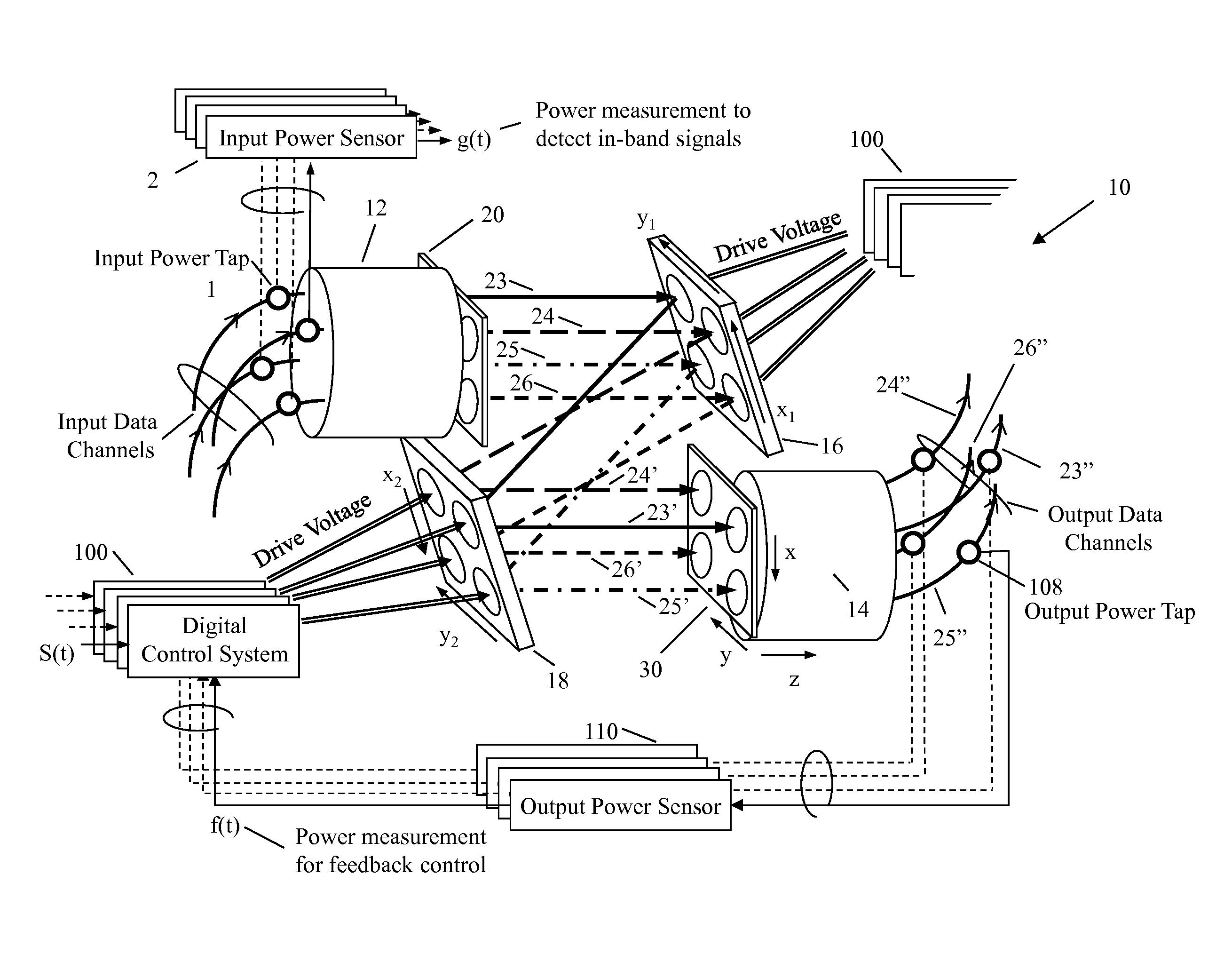
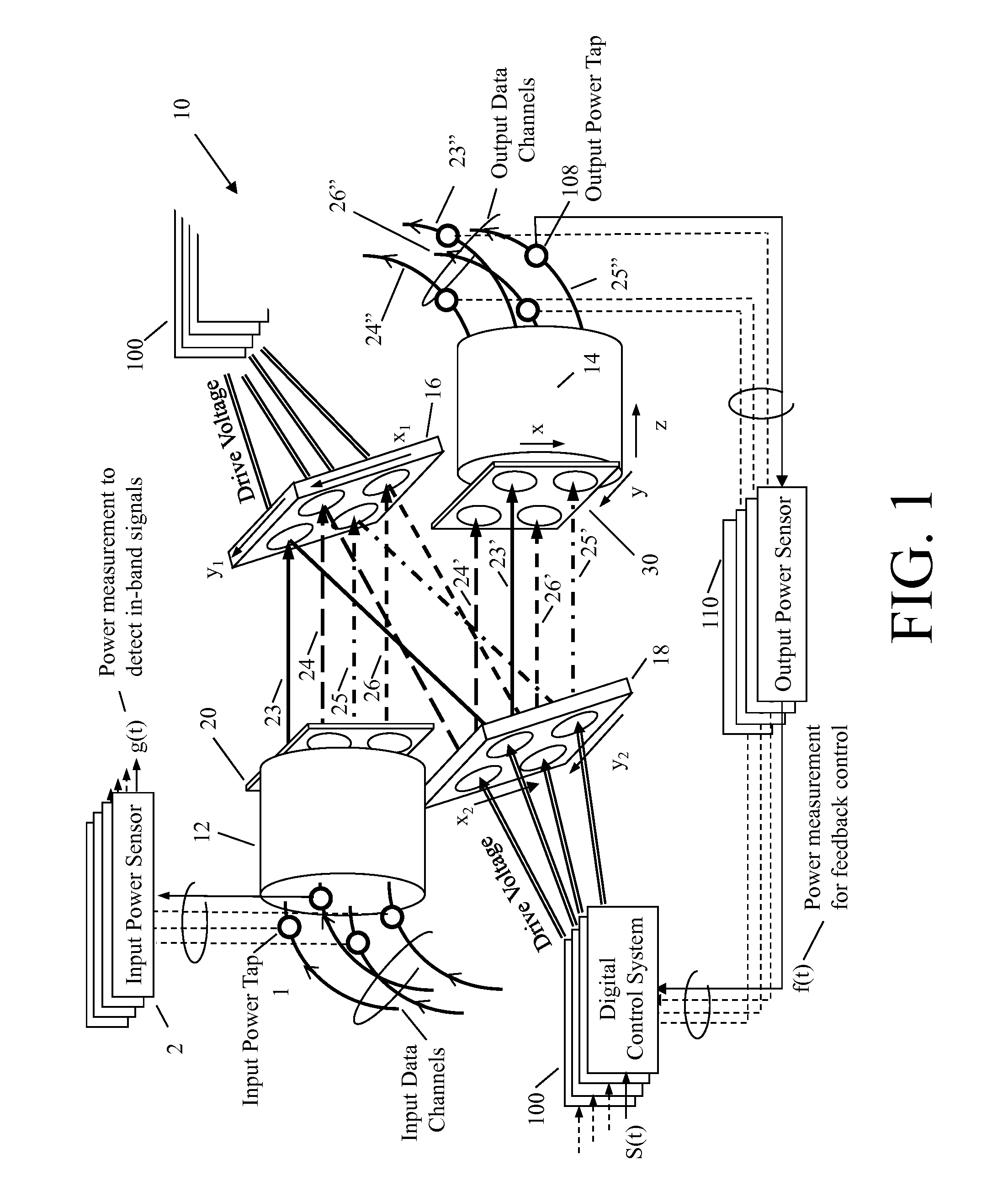
[0023]Referring to FIG. 1, there is shown an example of a four-port MEMS mirror array fiber-optic cross-connect switch 10 in which the present invention may be implemented. The function of the fiber-optic switch 10 is to produce desired free-space couplings between the input fibers, in a first fiber array 12, and output fibers, in a second fiber array 14, via two-axis steering mirrors on a first mirror array 16 and a second mirror array 18. In the embodiment illustrating the invention, the optical path is unidirectional between input fibers and output fibers. Laser beams emanating from the input fiber array 12 are substantially collimated using a first lens array 20 confronting the first fiber array 12. Mirrors on the first or input mirror array 16 steer collimated beams 23, 24, 25, 26 from the first lens array 20 toward the appropriate mirrors on the second or output mirror array 18. The mirrors on the output mirror array 18 steer the...


PUM


Abstract

In a multiple-axis free-space-coupled single-mode fiber-optic transmission system, such as an optical cross-connect switch, a method and apparatus are provided for the closed loop attenuation of optical beam power signals employed to align and cause dithering via MEMS mirrors which are manipulated to impose on the optical beam frequency modulation and, in particular, a time-varying set of induced mirror angles that yield a desired time history of optical power level that is modulated according to a digital code in the frequency modulation pattern.

Description

CROSS-REFERENCES TO RELATED APPLICATIONS[0001]The present application claims benefit under 35 USC 119(e) of U.S. provisional Application No. 61 / 560,393, filed on Nov. 16, 2011, entitled “IN-BAND SIGNALING IN OPTICAL CROSS-CONNECT SWITCH USING FREQUENCY MODULATION,” the content of which is incorporated herein by reference in its entirety.BACKGROUND OF THE INVENTION[0002]The invention relates to in-band signaling, and in particular to optical cross-connect switches providing an in-band signaling capability. The invention finds application to micro-electromechanical systems (MEMS), but it is not so limited.[0003]The optical cross-connect switch promises to become a key element of fiber-optic networks. Steering elements in the optical switch are used to direct beams of light from input fibers to the desired output fibers (or equivalently, optical waveguides). The amount of optical power coupled through a given connection is a function of a) the amount of power present in the input fiber...

Claims


Application Information

Patent Timeline
Patent Type & Authority Patents(United States)
IPC IPC(8): G02B26/00H04Q11/00
CPCG02B26/002H04Q11/0005H04Q2011/0039H04Q2011/003H04Q2213/1301H04Q2213/1302H04Q2213/1304H04Q2213/13396
Inventor CHAU, KELVIN
Owner GLIMMERGLASS NETWORKS
Why Eureka
Try Eureka