Dental implant guiding device

a guiding device and implant technology, applied in dental surgery, dental tools, medical science, etc., can solve the problems of inconvenient inconvenient placement and positioning of guiding modules, and damage to the motor of drilling apparatuses, etc., to facilitate the connection of guiding modules and facilitate placement and positioning

Inactive Publication Date: 2014-09-02
METAL INDS RES & DEV CENT
View PDF4 Cites 5 Cited by
  • Summary
  • Abstract
  • Description
  • Claims
  • Application Information

AI Technical Summary

Benefits of technology

[0009]It is therefore the main purpose of this invention to provide a dental implant guiding device, which improves the problem of hardly aiming accurately deriving from cooperating the guiding shanks with the guiding holes of the conventional guiding device.
[0010]The secondary purpose of this invention is to provide a dental implant guiding device, which improves the problem of the friction between the drill and the inner wall of the sleeve in surgery.
[0014]When the drill inserts into the cavity of the sleeve and the guiding seat sleeves on the drilling apparatus, the second guiding shank of the guiding seat easily slides in the guiding slot. After the second guiding shank is positioned, the first guiding shank inserts in the corresponding guiding hole. The guiding hole restrains the first guiding shank from slanting, and the guiding slot restrains the guiding seat from rotating about the first guiding shank as the center so that the drill is positioned in the middle of the sleeve, and the dental implant guiding device is adapted to different dimensions of drills without replacing the guiding unit. The sleeve of the guiding unit provides a larger cavity. By the combinations of the guiding hole and the first guiding shank as well as the guiding slot and the second guiding shank, the drill is positioned in the sleeve to prevent the apparatus from being broken by the friction formed between the drill and the sleeve. The second guiding shank laterally slides in the guiding slot for initially attaining a rapid placement and position, which facilitates a quick connection of the guiding module with the guiding seat for benefiting the surgery when the first guiding shank is accurately placed in the guiding hole.

Problems solved by technology

Wherein, when the diameter of the fixed sleeve is larger than the diameter of the drilling, the drill easily deviates from its original position while drilling, which results in the inaccuracy of the drilling orientation.
If the dimensions of the fixed sleeve and the drill are over closed, the friction formed between the drill and the inner fringe of the fixed sleeve would cause the motor of the drilling apparatus to be damaged, the drill to be overheated, and the debris resulted from the friction to be dropped in the surgical area.
Therefore, the fixed sleeve requires replacements according to different sizes of the drills, which is inconvenient in using.
The sizes of the guiding shanks and the guiding holes are small and hard to aim accurately.
The dimensions of the guiding unit is larger and the space of the rear teeth of the patient is smaller, so the guiding shank is much difficult to aim and insert to the guiding hole, and the drilling process becomes harder.
Moreover, the small sizes of the guiding shanks and the guiding holes are still difficult to aim with each other accurately.

Method used


Image

  • Dental implant guiding device
  • Dental implant guiding device
  • Dental implant guiding device

Examples


Embodiment Construction

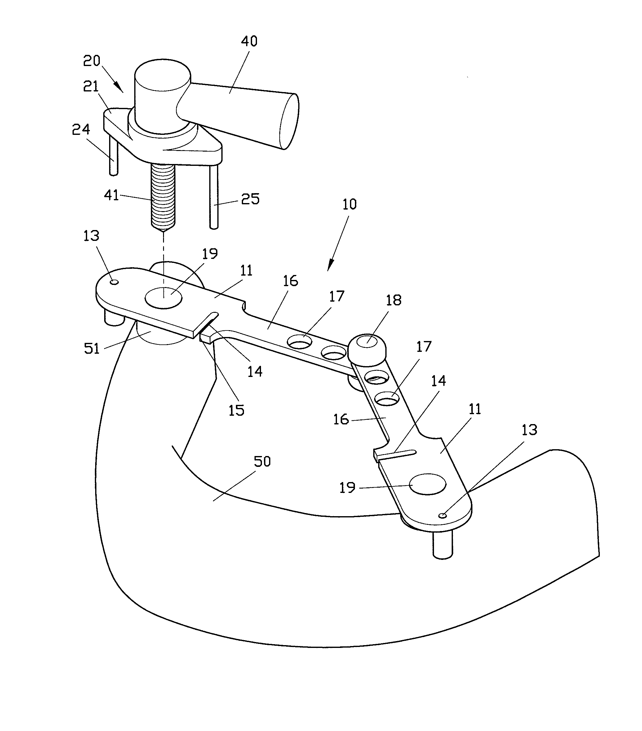
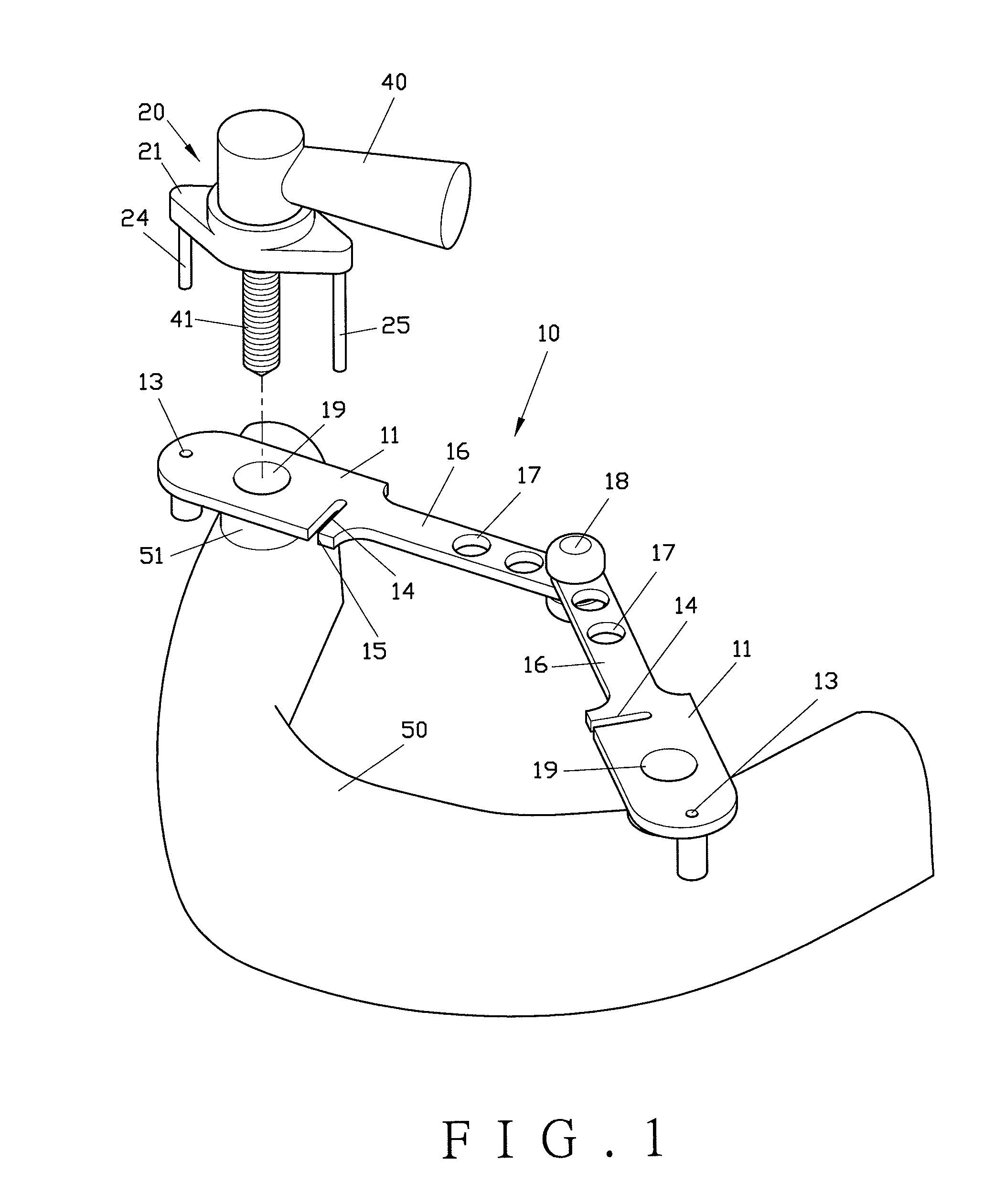
[0026]Referring to FIGS. 1, 2, and 3, a first preferred embodiment of the present is shown. The dental implant guiding device which is used to guide a drill 41 of a positioned drilling apparatus 40 for drilling the gums in the oral cavity comprises a guiding module 10 and a guiding seat 20.

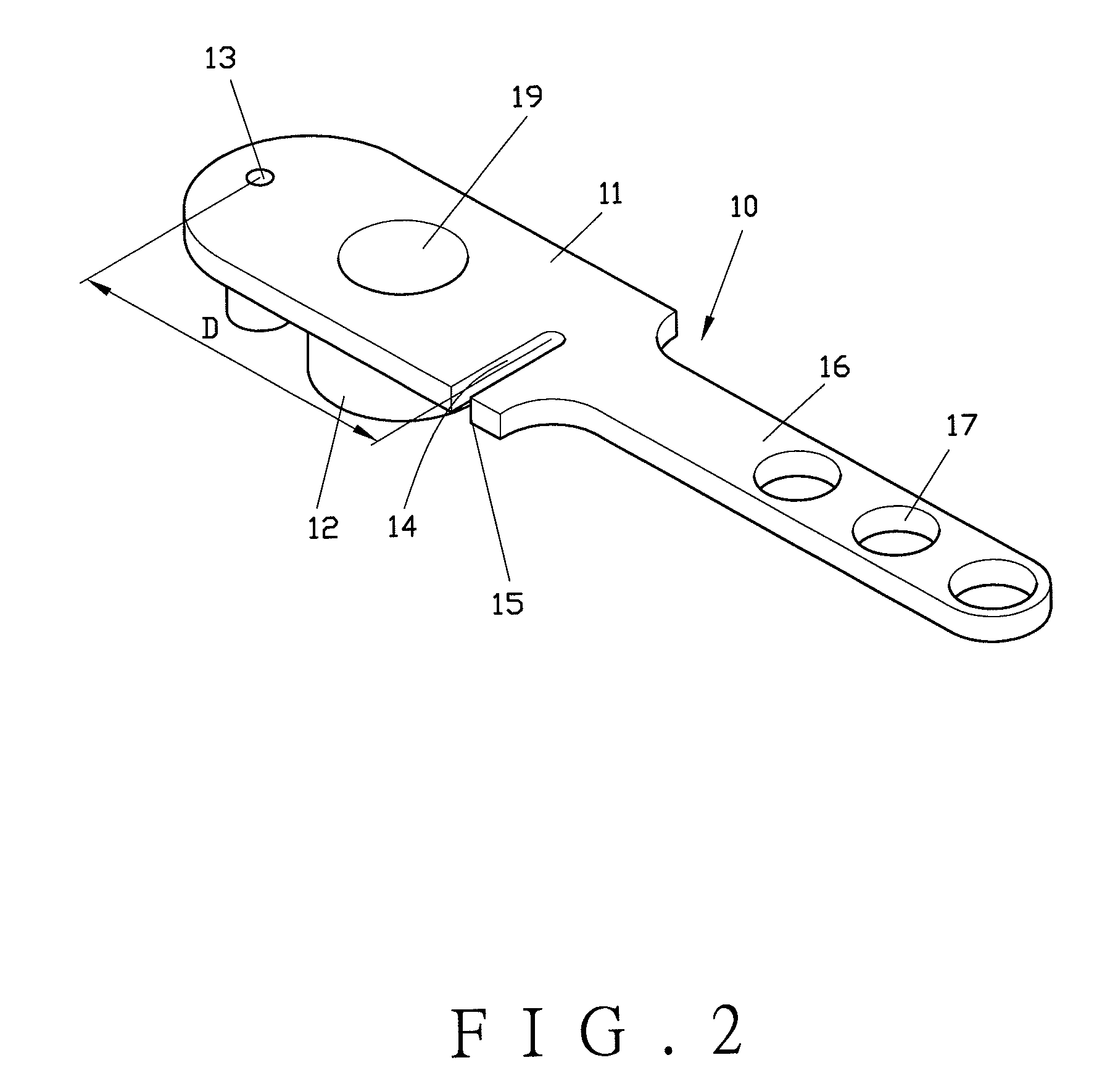
[0027]The guiding module 10 contains at least one guiding unit 11; wherein, a sleeve 12 is disposed on the guiding unit 11. The sleeve 12 has a cavity 19, and a guiding hole 13 and a guiding slot 14 are disposed at two sides of the sleeve 12, respectively; wherein, the guiding slot 14 forms an opening 15 defined at the outer fringe of the guiding unit 11. Preferably, the guiding slot 14 is a straight slot. Preferably, a side (or a closed side) opposite to the opening 15 of the guiding slot 14 is defined as an arc shape, and a center of the arc is aligned with a center of the sleeve 12 (or the cavity 19) and a center of the guiding hole 13. In the first preferred embodiment of the present invention...


PUM


Abstract

A dental implant guiding device is applied in guiding the drill of the drilling apparatus in different dimensions. The device includes a guiding module and a guiding seat. The guiding module contains at least one guiding unit where a sleeve with a cavity is disposed. A guiding hole and a guiding slot, where an opening at a fringe of the guiding unit is defined, are disposed at two sides of the sleeve. The guiding seat forms a first hole. At two sides of the first hole, a first guiding shank and a second guiding shank respectively corresponding to the guiding hole and the guiding slot are disposed. The second guiding shank slides into the guiding slot, which allows the first guiding shank inserting into the guiding hole for the drill to position at the center of the cavity of the sleeve, thereby achieving the fast positioning and friction reduction.

Description

BACKGROUND OF THE INVENTION[0001]1. Field of the Invention[0002]The present invention relates to a guide device, in particular to a dental implant guiding device that is convenient to doctors in surgery.[0003]2. Description of the Related Art[0004]For the accuracy of the drilling orientation in dental implant, a surgical guiding plate is prefabricated to co-operate the teeth construction of the patients. A fixed sleeve is disposed on the surgical guiding plate, and then the doctor holds a drilling apparatus with the drill and places the drill into the fixed sleeve to proceed drilling. Wherein, when the diameter of the fixed sleeve is larger than the diameter of the drilling, the drill easily deviates from its original position while drilling, which results in the inaccuracy of the drilling orientation. If the dimensions of the fixed sleeve and the drill are over closed, the friction formed between the drill and the inner fringe of the fixed sleeve would cause the motor of the drilli...

Claims


Application Information

Patent Timeline
Patent Type & Authority Patents(United States)
IPC IPC(8): A61C3/02
CPCA61C1/084
Inventor LO, KAI-SZULIU, YAUCHIAHUANG, CHING-CHIEHKUO, HSIEN-NAN
Owner METAL INDS RES & DEV CENT
Why Eureka
Try Eureka