Ligating instrument

a ligating instrument and ligating technology, applied in the field of medical ligating instruments, can solve the problems of improper calibration of the device, tissue death and sloughing, etc., and achieve the effect of simplifying the setup

Active Publication Date: 2014-09-02
BOSTON SCI SCIMED INC
View PDF16 Cites 2 Cited by
  • Summary
  • Abstract
  • Description
  • Claims
  • Application Information

AI Technical Summary

Benefits of technology

[0011]It will be appreciated that having a ligating instrument in which a pull line is not threaded through an endoscope lumen provides for simplified set-up. It will be appreciated that, in such embodiments, it may be provided such that there is no need for the user to tie or otherwise connect a free end of the pull line to an actuator mechanism. Also, the ligating device may be provided such that no additional calibration by the user is required.
[0012]It will also be appreciated that, in certain embodiments of the invention, the ligating instrument may be provided as a single functional unit. It can be mounted on the endoscope as a single functional unit or used independently. In addition, the distal ligating band dispenser may be mounted on the distal end of an endoscope while the proximal actuator member is not mounted on the endoscope, allowing for operation of the ligating instrument remote from and / or independent from the endoscope.

Problems solved by technology

For example, the physician can remove target tissue by ligating it to obstruct all circulation through the target tissue, thereby causing the tissue to die and slough off.
The process of threading the wire or string and attaching it to the actuator mechanism adds additional steps in setting-up the instrument for use and can be cumbersome.
It can also lead to error and improper calibration of the device.

Method used


Image

  • Ligating instrument
  • Ligating instrument
  • Ligating instrument

Examples


Embodiment Construction

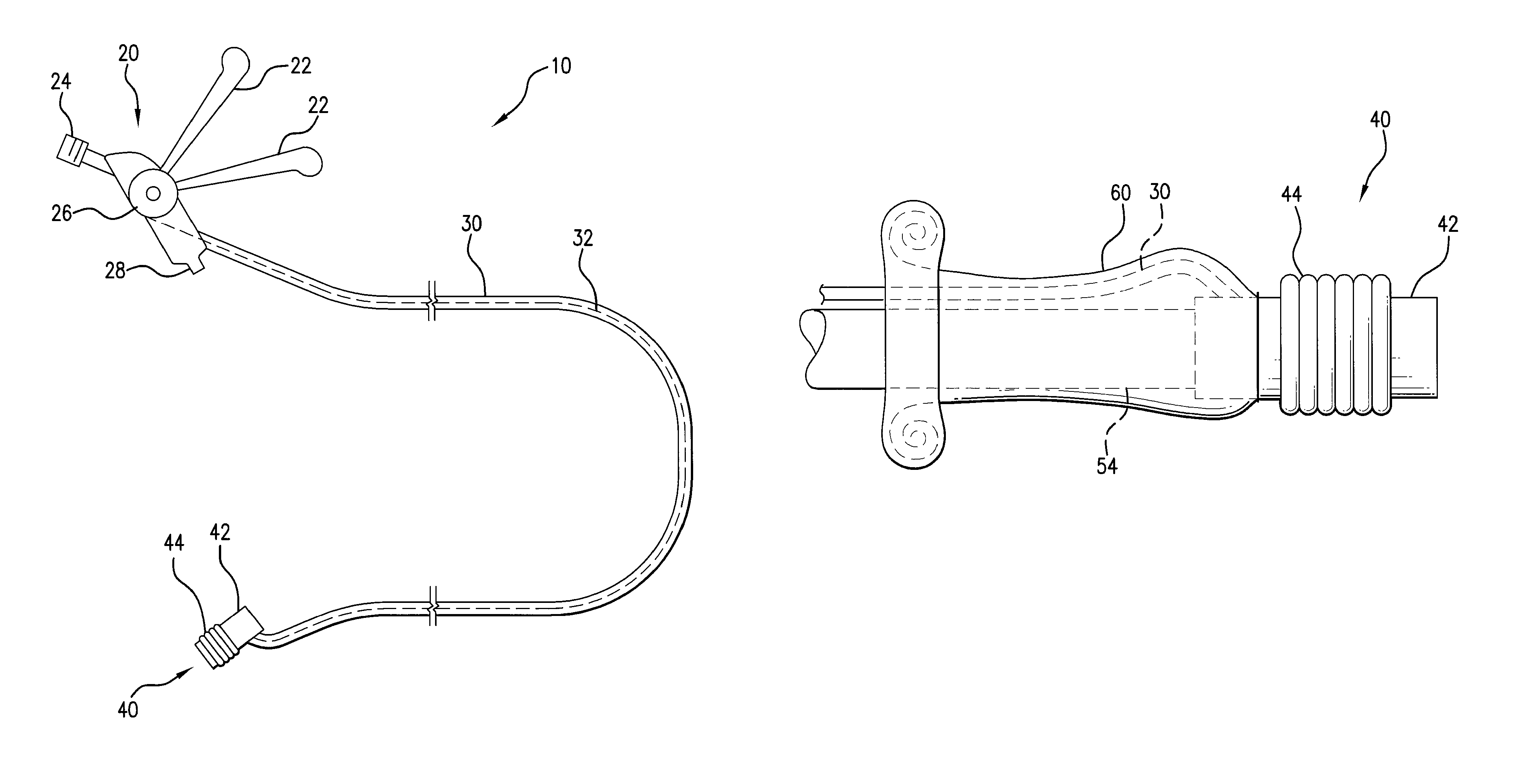
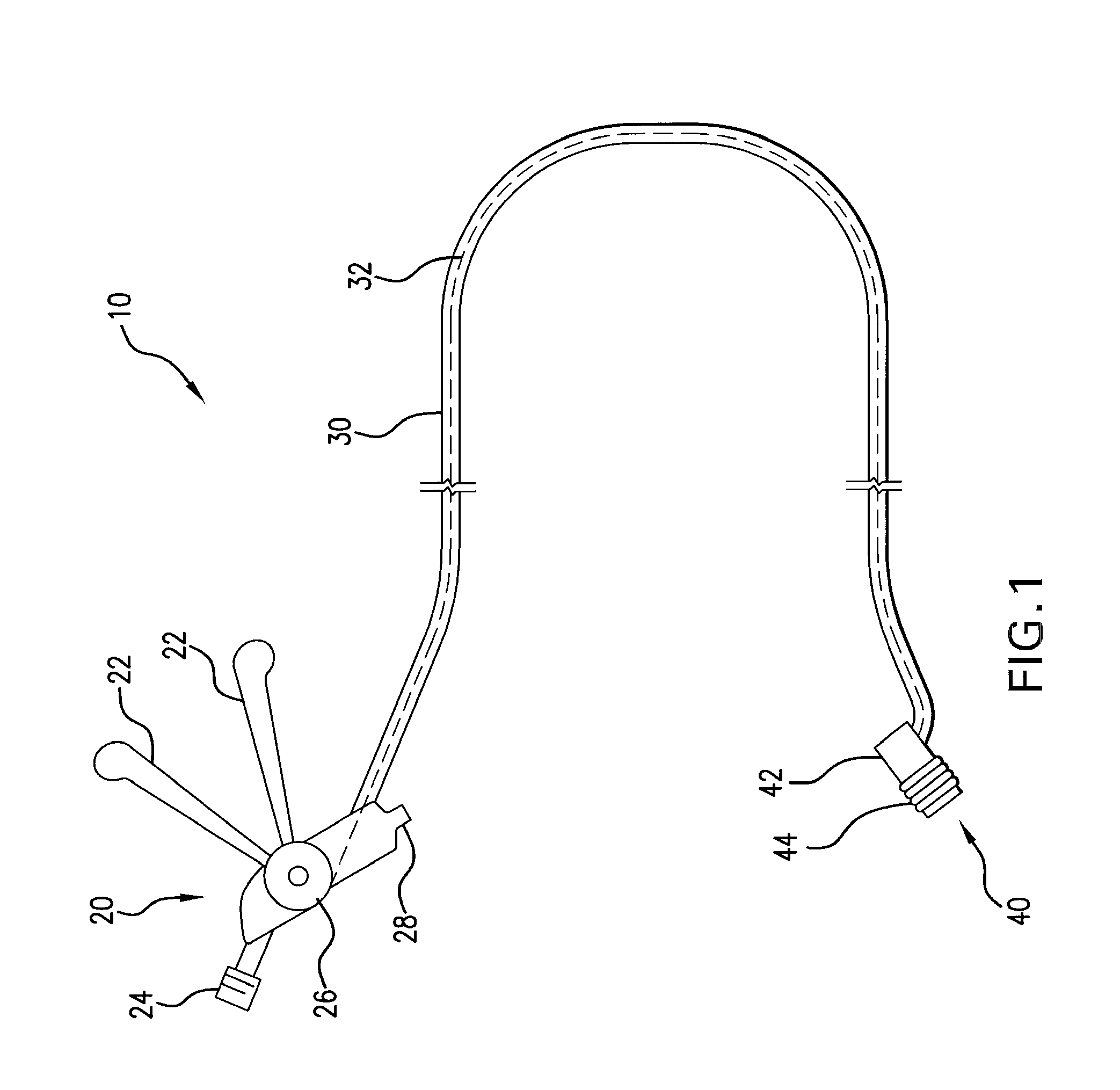
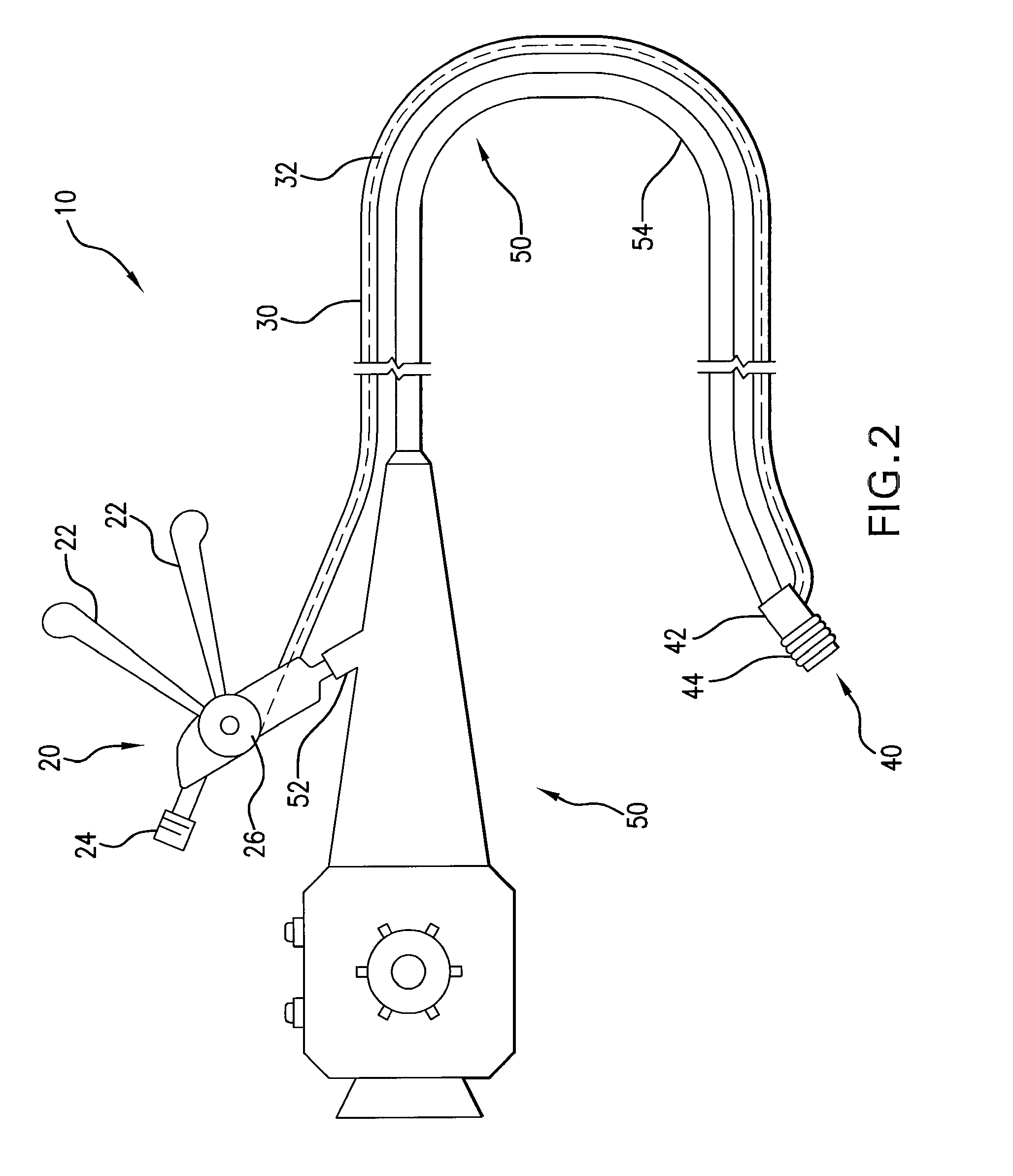
[0020]A ligating instrument 10 in accordance with one possible embodiment of the present invention is illustrated in FIG. 1. At the distal end of the instrument 10 is a ligating band dispenser 40 that dispenses ligating bands 44. In this embodiment, the ligating band dispenser 40 is adapted to be coupled to the distal tip of an endoscope 50 and includes a plurality of ligating bands 44 that are released by the drawing of a pull line 32 in the form of a wire or string.

[0021]FIG. 7 shows one possible embodiment of the ligating band dispenser 40. This embodiment of the ligating band dispenser 40 includes a support structure 42, which may be substantially cylindrical. The ligating band dispenser may be designed to be attached to the distal end of an endoscope. For example, a central bore 46 (visible in FIG. 5) in the ligating band dispenser 40 may be adapted to receive the distal tip of an endoscope tube 54.

[0022]A plurality of ligating bands 44 are received around the support structure...


PUM


Abstract

A ligating instrument is provided, including an elongate member, such as a tube, having a lumen, the elongate member extending from a proximal actuator member to a distal ligating band dispenser. A pull line may extend through the lumen of the elongate member, with a proximal end of the pull line connected to the actuator member and a distal end of the pull line connected to the ligating band dispenser, wherein actuation of the actuator member draws the pull line in a proximal direction through the elongate member to deploy the ligating bands. The ligating band dispenser may be adapted to be mounted on the distal tip of an endoscope, and the elongate member may be adapted to be positioned outside of the endoscope from the ligating band dispenser to the actuator member. Alternatively, a ligating instrument may be provided for use with an endoscope, wherein a pull line of the ligating instrument is adapted to be positioned outside of the endoscope, wherein the pull line may be secured to the endoscope by clips or some other means. In a method of using a ligating instrument with an endoscope, a distal ligating band dispenser is attached to a distal tip of an endoscope, and a pull line of the ligating instrument is extended on the outside of the endoscope, such that the pull line extends, on the outside of the endoscope, from the distal ligating band dispenser to a proximal actuator member.

Description

TECHNICAL FIELD[0001]The present invention relates to medical ligating instruments and more particularly to medical ligating instruments that dispense ligating bands.BACKGROUND OF THE INVENTION[0002]Ligation is a medical procedure whereby the physician ties off or mechanically constricts a piece of body tissue with an encircling ligature such as a suture, clip, or elastic band. The purpose of ligation is to impede or obstruct the flow of blood, fluids, and other bodily materials through the tissue. For example, the physician can remove target tissue by ligating it to obstruct all circulation through the target tissue, thereby causing the tissue to die and slough off.[0003]For ligating tissue inside a body cavity, orifice, or lumen, physicians often use an endoscope to access the target tissue and ligate it. In one such form of endoscopic ligation, the physician uses the endoscope to position a stretched elastic band over the target tissue and then release the band onto the tissue so...

Claims


Application Information

Patent Timeline
Patent Type & Authority Patents(United States)
IPC IPC(8): A61B17/10
CPCA61B2017/00292A61B2017/12018A61B17/12013
Inventor RICHARDSON, M., KEVIN
Owner BOSTON SCI SCIMED INC
Why Eureka
Try Eureka