Display processing apparatus, image forming system, display processing method, and computer-readable storage medium

a display processing and display technology, applied in the field of display processing apparatus, image forming system, display processing method, computer-readable storage medium, can solve the problems of inability to realize the preview display near to the actual print result, the difference between the actual print result and the preview display becomes large,

Active Publication Date: 2014-09-02
RICOH KK
View PDF7 Cites 2 Cited by
  • Summary
  • Abstract
  • Description
  • Claims
  • Application Information

AI Technical Summary

Benefits of technology

[0008]It is an object of the present invention to at least partially solve the problems in the conventional technology.

Problems solved by technology

However, in the technology disclosed in Japanese Patent Application Laid-open No. 2008-145784, when a designated surface effect cannot be realized by a device configuration of a printer and the like, a difference between an actual print result and a preview display becomes large.
That is, a problem arises in that a preview display near to an actual print result cannot be realized depending on a device configuration of a printer.

Method used


Image

  • Display processing apparatus, image forming system, display processing method, and computer-readable storage medium
  • Display processing apparatus, image forming system, display processing method, and computer-readable storage medium
  • Display processing apparatus, image forming system, display processing method, and computer-readable storage medium

Examples


first embodiment

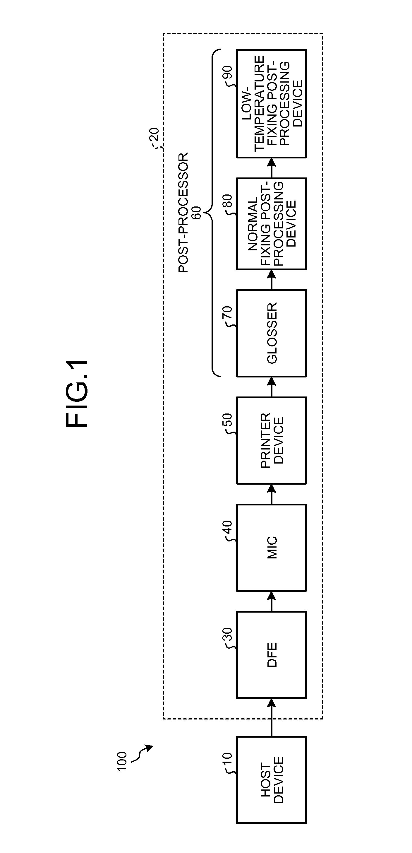
[0051]FIG. 1 is a block diagram illustrating of an example of a schematic configuration of an image forming system 100 according to the embodiment. As illustrated in FIG. 1, the image forming system 100 includes a host device 10 and a printing apparatus 20.

Configuration of Printing Apparatus

[0052]For the convenience of explanation, first, a specific configuration of the printing apparatus 20 will be explained. The printing apparatus 20 is configured by connecting a digital front end (DFE) 30, a mechanism I / F controller (MIC) 40, a printer device 50, a post-processor 60.

[0053]The DFE 30 communicates with the printer device 50 via the MIC 40 and controls image formation in the printer device 50. Further, the DFE 30 is connected with the host device 10 to be described later. The DFE 30 receives print data to be described from the host device 10 and generates image data for forming a toner image according to respective CMYK toners and a colorless (transparent color) clear toner based on...

second embodiment

[0146]Next, a second embodiment will be explained. In the second embodiment, a table number is specified according to device configuration information and number of times information to be described later and a surface effect selection table corresponding to the table number is disposed to each of the host device 10 and the DFE 30. Hereinafter, a portion different from the first embodiment will be mainly described. A portion common to the first embodiment is denoted by the same reference numeral and an explanation thereof is appropriately omitted.

[0147]FIG. 24 is a view illustrating an example of a schematic configuration of a printing apparatus 20 of the second embodiment. As illustrated in FIG. 24, the printing apparatus 20 includes a first conveying path 150, a second conveying path 160, and a switching unit 170. The first conveying path 150 is a conveying path for conveying a recording medium from the printer device 50 to the post-processor 60 and conveying the recording medium ...

third embodiment

[0168]In respective embodiments described above, although the host device 10 is configured to execute the preview image display process, the embodiments are not limited thereto.

[0169]That is, the embodiments may be configured such that any of plural processes executed by a device is executed by at least a device connected to the device via a network.

[0170]As an example of the configuration, an image forming system according to the embodiment mounts a part of a function of a host device on a server device on a network.

[0171]FIG. 30 is a view exemplifying a configuration of an image forming system 100D according to the embodiment. As illustrated in FIG. 30, the image forming system 100D includes a host device 110 and the printing apparatus 20.

[0172]The embodiment is configured such that the host device 110 is connected to a server device 3060 via a network such as the Internet, and the like. Further, in the embodiment, functions of a plane data generating unit 122, a print data genera...


PUM


Abstract

A display processing apparatus includes a gloss-control plane generating unit configured to generate gloss-control plane data for specifying a type of a surface effect applied to a recording medium and an area in a recording medium to which the surface effect is applied; an obtaining unit configured to obtain replacement information that is used to replace a type of the surface effect that is not available in a device configuration with a type of the surface effect that is available in the device configuration; a replacing unit configured to replace the type of the surface effect designated by the designation information with the type of the available surface effect using the replacement information obtained by the obtaining unit; and a preview image generating unit configured to generate a preview image based on the gloss-control plane data having an area to which the available surface effect is to be applied.

Description

CROSS-REFERENCE TO RELATED APPLICATIONS[0001]The present application claims priority to and incorporates by reference the entire contents of Japanese Patent Application No. 2011-201107 filed in Japan on Sep. 14, 2011 and Japanese Patent Application No. 2012-180281 filed in Japan on Aug. 15, 2012.BACKGROUND OF THE INVENTION[0002]1. Field of the Invention[0003]The invention relates to a display processing apparatus, an image forming system, a display processing method, and a computer-readable storage medium.[0004]2. Description of the Related Art[0005]Conventionally, there is an image forming apparatus mounted with a clear toner that is a colorless toner containing no color material except CMYK four-color toners. A toner image formed by the clear toner is fixed on a recording medium on which an image is formed by the CMYK toners. As a result, a visual effect and a tactual effect (called surface effect) are realized on a surface of the recording medium. In the image forming apparatus, ...

Claims


Application Information

Patent Timeline
Patent Type & Authority Patents(United States)
IPC IPC(8): G06K1/00
CPCG03G15/6585G03G2215/0081G06F3/1205G06K15/1867G03G15/502G06F3/1255G06F3/1256
Inventor MOCHIZUKI, TOSHIHIRO
Owner RICOH KK
Why Eureka
Try Eureka