
Juicer module and vertical screw juicer

a juicer and screw technology, applied in the field of juicer modules, can solve the problems of difficult cleaning of the inner portion of the cylindrical protrusion on the central bottom portion of the juicer container and the internal portion of the cylindrical depression on the lower portion of the screw, and the disadvantage is very critical, so as to facilitate the cleaning of the juicer and facilitate the cleaning of the lid

Inactive Publication Date: 2014-09-09
NUC ELECTRONICS
View PDF47 Cites 21 Cited by
  • Summary
  • Abstract
  • Description
  • Claims
  • Application Information

AI Technical Summary

Benefits of technology

This design enhances cleaning efficiency, prevents moisture leakage, and stabilizes the screw, ensuring better sanitation and juicing performance by eliminating the need for a shaft socket and reducing the risk of breakage.

Problems solved by technology

However, this type of juicer has typically been restricted to crushing tough materials such as green vegetables composed of stems or leaves to produce vegetable juices.
However, this type of conventional juicer has a disadvantage in that it is difficult to clean the surrounding of the cylindrical protrusion on the central bottom portion of the juicer container and the internal portion of the cylindrical depression on the lower portion of the screw.
Since the juicer is a food processing device requiring extreme cleanness, this disadvantage is very critical.
Although the fluctuation of the screw may be prevented by inserting the shaft formed on the upper portion of the screw into the shaft socket formed in the lid according to the most popular scheme in the food processing field, there is another disadvantage in that the shaft socket formed in the lid may be broken under the unstable assembling condition of the screw.
Further, it is very inconvenient to clean the shaft socket formed on the lid, and this is deemed to be a disadvantage for such a food processing device requiring sanitation.

Method used


Image

  • Juicer module and vertical screw juicer
  • Juicer module and vertical screw juicer
  • Juicer module and vertical screw juicer

Examples


Embodiment Construction

[0039]Hereinafter, embodiments of the present invention will be described in detail with reference to the accompanying drawings. The embodiments described herein are merely provided as examples to completely convey the sprit and scope of the present invention to those skilled in the art. Accordingly, the present invention is not be limited to the embodiments to be described below but may be implemented in various different forms. And, widths, lengths and thicknesses of the components may be represented in an exaggerative manner for convenience through the drawings. Through the specification, like elements are designated by like reference numerals.

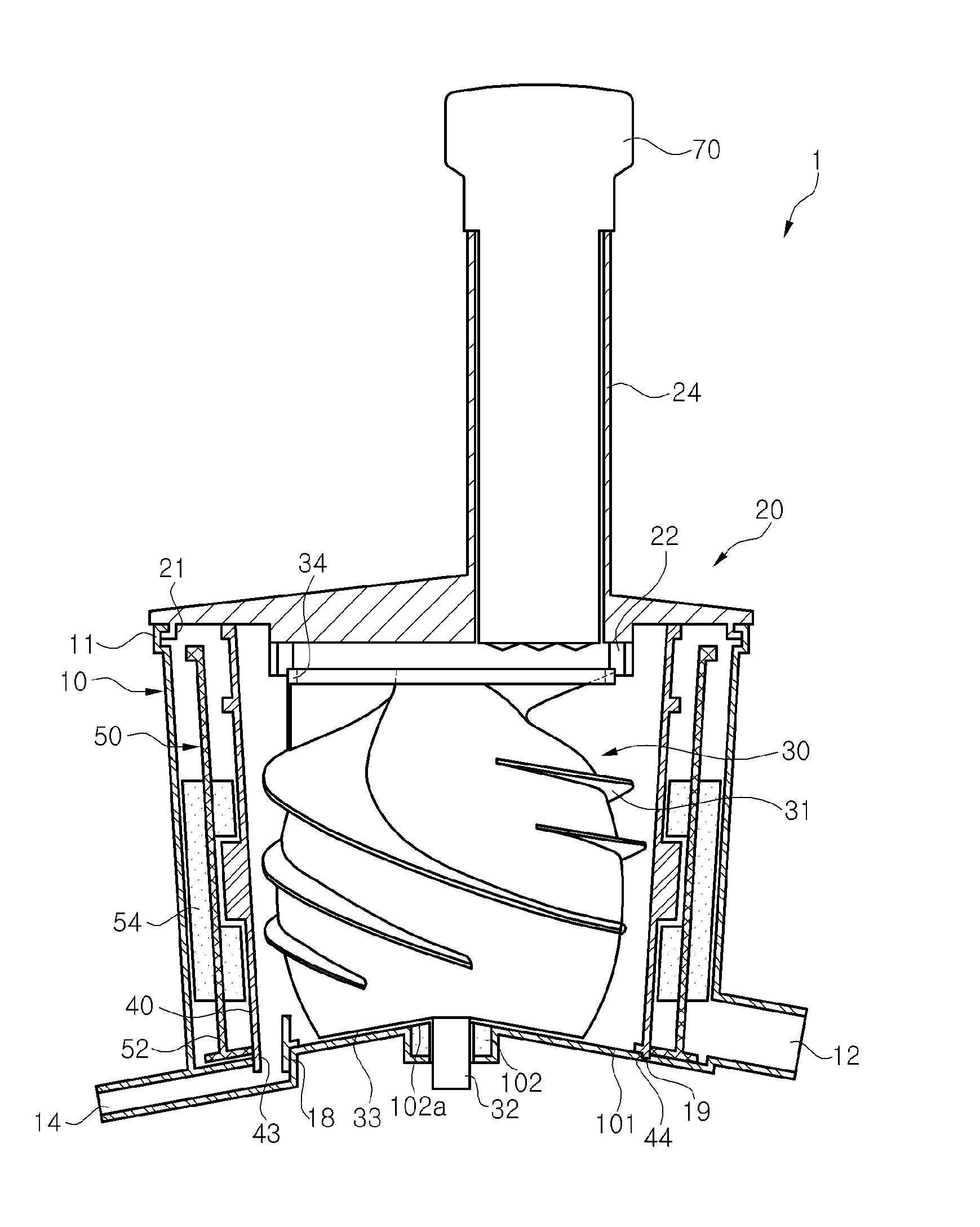
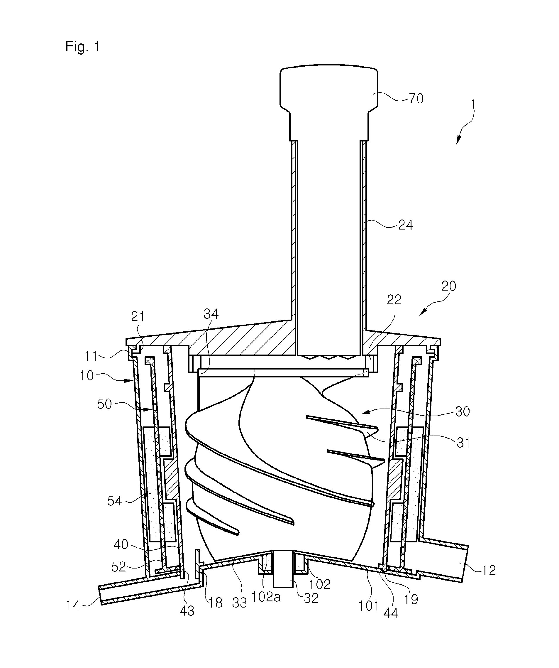
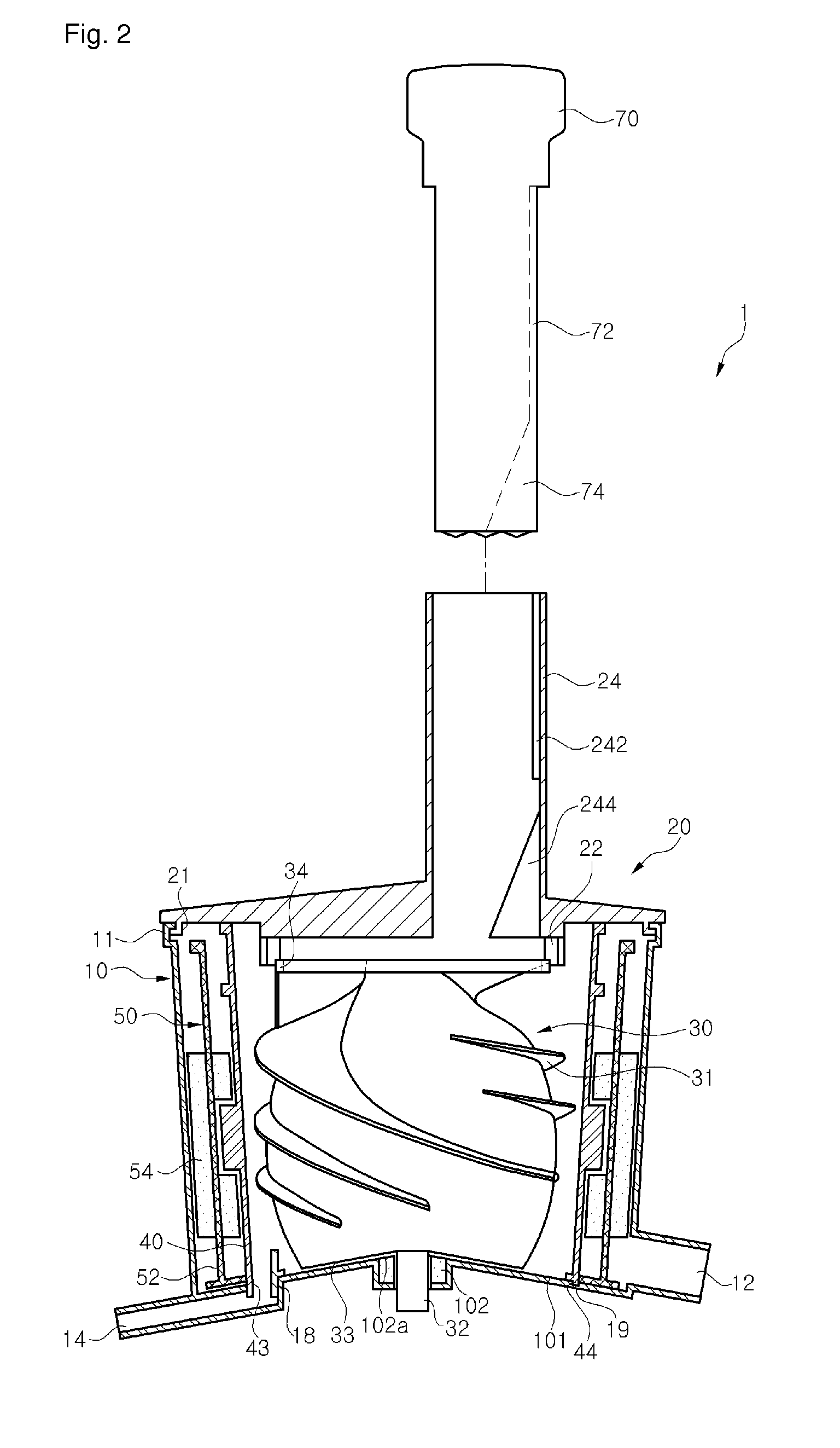
[0040]FIG. 1 is a sectional view illustrating a juicer module according to an embodiment of the present invention; FIG. 2 is an exploded sectional view illustrating the juicer module from which a squeezing rod is decoupled; FIG. 3 is a perspective view illustrating a screw of the juicer module shown in FIG. 1; and FIG. 4 is a view illustrat...


PUM


Abstract

A juicer module is disclosed herein. The juicer module includes an open top juicer container, a lid which is provided with a material input through a side of the lid and coupled to an upper portion of the juicer container, a net drum fixedly arranged within the juicer container and a screw arranged within the net drum. The screw is provided with a spiral portion formed on a side surface of the screw and a rotary shaft to pass through the shaft hole of the juicer container. The juicer module may further include a guide rotary portion formed on an upper end of the screw, and the lid may be provided with a rotary guide for guiding the rotation of the screw, the rotary guide being in contact with an edge of the guide rotary portion when the juicer module is assembled.

Description

BACKGROUND[0001]1. Technical Field[0002]The present disclosure relates to a juicer module, and more particularly, to a juicer module in which a screw connected to a driving shaft of a driving device is used to squeeze and / or mill vegetables, fruits, nuts, cereals, etc., thereby producing juices, vegetable juices or other juice-type foods.[0003]2. Description of the Related Art[0004]A juicer is a device for processing vegetables, fruits, etc. to produce fluid-typed or juice-typed foods. Various types of juicers which may be conveniently used for domestic or commercial applications have been known. Most universal juicers adopted a scheme in which a material is thrown into a material input and then milled by using a high-speed rotary blade. However, this type of juicer has typically been restricted to crushing tough materials such as green vegetables composed of stems or leaves to produce vegetable juices.[0005]Accordingly, a juicer has been conventionally developed to squeeze vegetabl...

Claims


Application Information

Patent Timeline
Patent Type & Authority Patents(United States)
IPC IPC(8): A23N1/00A47J19/02
CPCA47J19/027A47J19/025
Inventor KIM, JONG, BOO
Owner NUC ELECTRONICS
Learn More