Heat exchanger and heat exchanging system

a heat exchanger and heat exchange technology, which is applied in the direction of indirect heat exchangers, refrigeration components, light and heating apparatus, etc., can solve the problems of reducing heat exchange coefficient, achieve steady and efficient heat transfer, enhance heat exchange efficiency, and improve heat exchange efficiency

Inactive Publication Date: 2014-09-09
SHARP KK
View PDF24 Cites 13 Cited by
  • Summary
  • Abstract
  • Description
  • Claims
  • Application Information

AI Technical Summary

Benefits of technology

[0025]According to the present invention, the fins have the concave and convex parts that extend in a direction intersecting the flow direction of the second fluid, so that a portion of the second fluid passing between the fins forms a vortex in the concave part. Furthermore, the flow rate of the second fluid is made variable at a regular cycle, thereby providing an effect that heat transfer between the second fluid and the fins or the tube is enhanced via a vortex in the concave part. In addition, stagnation of the second fluid in the concave part and renewal of the second fluid in the concave part occur repeatedly, and thus heat transfer is performed steadily and efficiently. Thus, without dependence on heat conduction performance of the fins themselves, a region used for heat exchange between the fins and a flow between the fins can be spread throughout a surface of the fins, thereby allowing an improvement in heat exchange efficiency.

Problems solved by technology

The above-described finned tube-type heat exchanger 1 according to the conventional technique has presented a problem that, on a downstream side of the fins 3, a boundary layer of a flow in the vicinity of a surface of the fins 3 has an increased thickness, causing a decrease in heat transfer coefficient.

Method used


Image

  • Heat exchanger and heat exchanging system
  • Heat exchanger and heat exchanging system
  • Heat exchanger and heat exchanging system

Examples


first embodiment

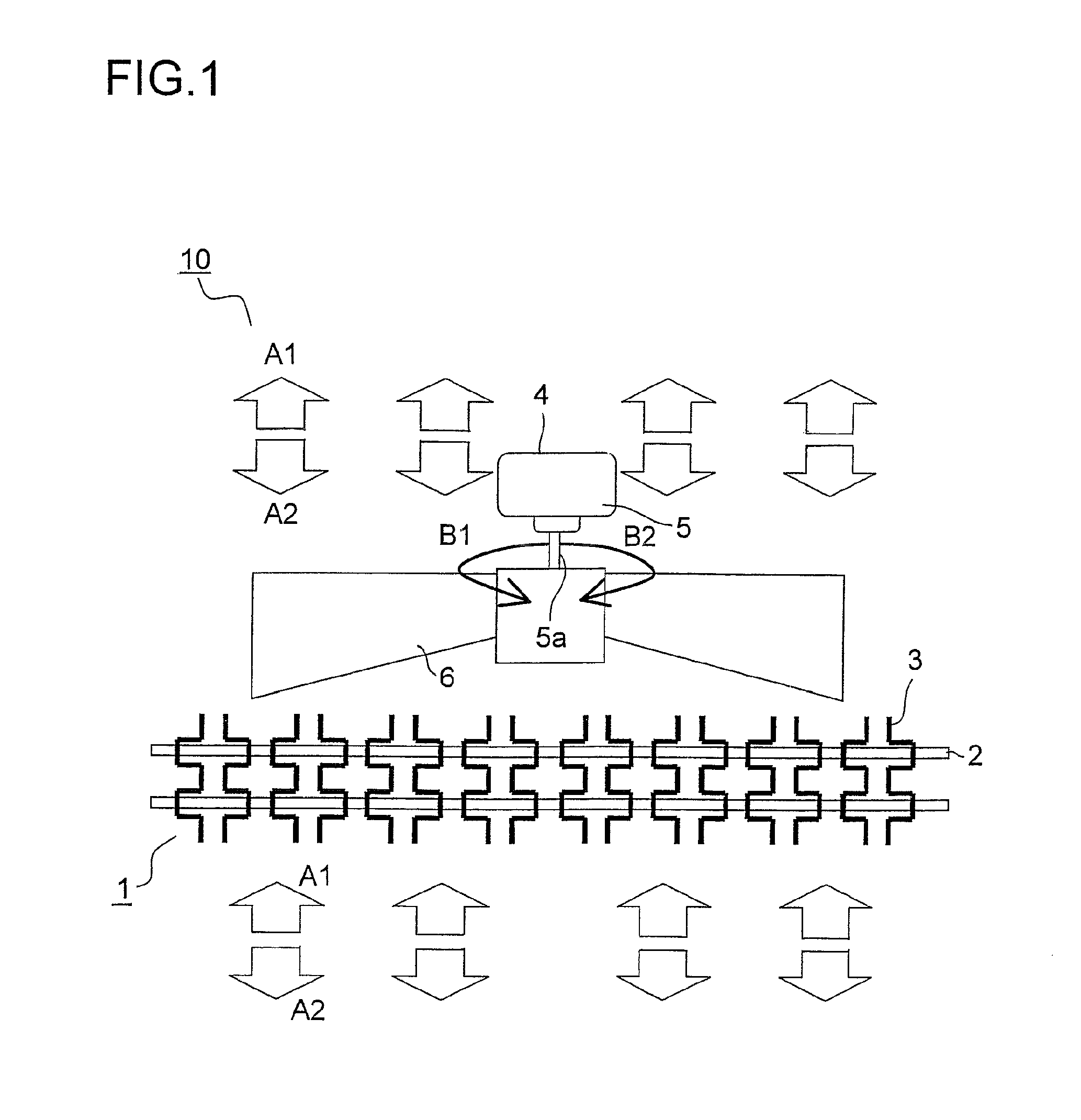
[0054]The following describes an embodiment of the present invention with reference to the appended drawings. FIG. 1 is a schematic structural view showing a heat exchanging system according to a first embodiment. A heat exchanging system 10 includes a heat exchanger 1 and a fan 4. The heat exchanger 1 has a tube 2 for a first fluid such as water, CO2, or a HCF-based refrigerant to flow therethrough and a fin 3 attached to the tube 2, and thus is of a finned tube-type.

[0055]The heat exchanging system 10 is placed in a second fluid such as air. A fan 4 is formed of an axial flow fan such as a propeller fan and has a vane 6 attached to a motor shaft 5a of a motor 5. In accordance with electric power used to drive the motor 5, the rpm (rotation speed) of the vane 6 changes sinusoidally, i.e. at a regular cycle, the rpm of the vane 6 is increased and decreased and the rotation direction thereof is inverted.

[0056]In this configuration, when the vane 6 rotates in a direction indicated by ...

second embodiment

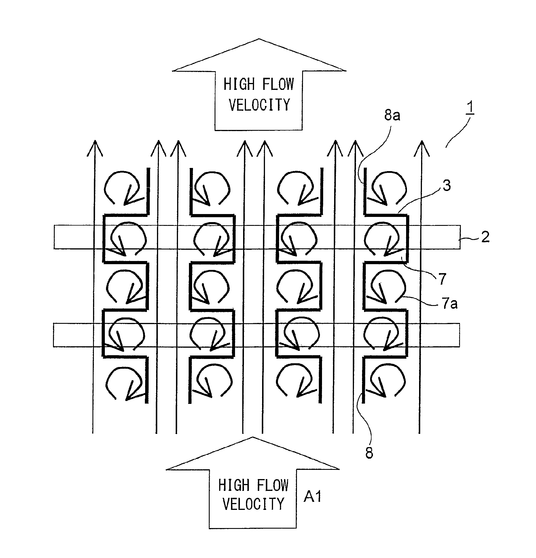
[0078]The description is next directed to a heat exchanging system 10 according to a second embodiment. This embodiment has a configuration similar to the previously described configuration of the first embodiment shown in FIG. 1 and is different therefrom in arrangement of fins 3. FIGS. 8 to 12 are top views explaining states where a second fluid passes through a heat exchanger 1. In the heat exchanger 1, a concave part 7 and a convex part 8 of the fin 3 are arranged so that the concave part 7 of each of the fins 3 faces the convex part 8 of an adjacent one of the fins 3. Parts other than these are configured similarly to those of the first embodiment.

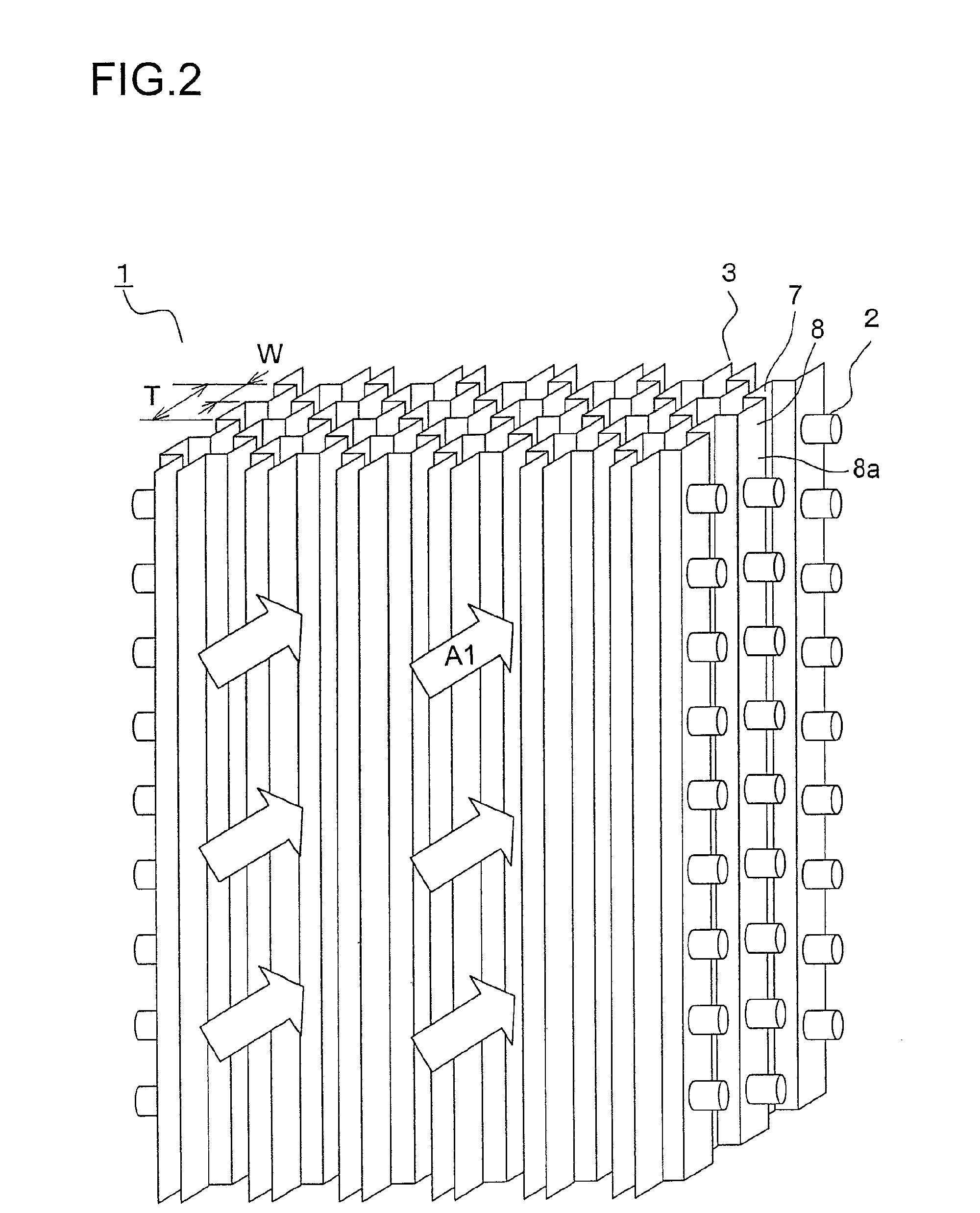
[0079]FIG. 8 shows a state of the second fluid passing between the fins 3 at a maximum flow velocity. A Reynolds number Re obtained at this time with respect to a width W of the concave part 7 (see FIG. 2) as a representative length has a value larger than a critical Reynolds number.

[0080]A main flow direction of the second fluid flow...

third embodiment

[0091]FIG. 13 is a schematic structural view showing a heat exchanging system according to a third embodiment. For the sake of convenience of explanation, like reference symbols denote parts corresponding to those of the previously described first embodiment shown in FIG. 1. In a heat exchanging system 11 according to this embodiment, a vane 6 of a fan 4 is configured differently from the first embodiment. Parts other than this are configured similarly to those of the first embodiment.

[0092]The fan 4 is formed of an axial flow fan, and the vane 6 is composed of vane blades 6a and 6b having mutually opposite angles of attack, which are arranged alternately in a rotation direction. The fan 4 is driven at a constant rpm, and in the figure, with respect to a left side portion of a heat exchanger 1 opposed to the vane blade 6a, a second fluid is introduced thereto in a direction indicated by an arrow A3. In the figure, with respect to a right side portion of the heat exchanger 1 opposed ...


PUM


Abstract

A heat exchanging system (10) comprises a heat exchanger (1) including a tube (2) through which a first fluid flows and a plurality of fins (3) made from thin plates attached to the tube (2) and arranged parallel to each other in the direction along which the tube (2) extends, and a fan (4) for introducing a second fluid between the fins (3). The fin (3) includes concave parts (7) and convex parts (8) continuously and cyclically formed in a zigzag line. The concave parts (7) and the convex parts (8) are so arranged as to extend in the direction crossing the flow direction of the second fluid flowing between the fins (3), and the flow of the second fluid flowing between the fins (3) is made to be cyclically variable.

Description

TECHNICAL FIELD[0001]The present invention relates to a finned tube-type heat exchanger and a heat exchanging system using the same.BACKGROUND ART[0002]FIG. 28 shows a finned tube-type heat exchanger according to the conventional technique. In a heat exchanger 1, a plurality of thin plate-shaped fins 3 are attached to a tube 2 for a fluid to flow therethrough. In general, a fluid having a high heat transfer coefficient (such as, for example, water, CO2, or a HCF-based refrigerant) is passed inside the tube 2, and a fluid having a low heat transfer coefficient (such as, for example, air) is passed outside the tube 2.[0003]The fins 3 are arranged side by side in the extending direction of the tube 2, and heat exchange is performed between a fluid flowing through the tube 2 and a fluid supplied between the fins 3 as indicated by an arrow A1. On the outside of the tube 2, which has a low heat conductivity, the fins 3 increase a heat exchange area and thus allow a large heat exchange amo...

Claims


Application Information

Patent Timeline
Patent Type & Authority Patents(United States)
IPC IPC(8): F28F1/14F28D1/03F28F1/12F28F1/32
CPCF28F1/32F28F1/126F28F2250/08F25B2600/11
Inventor SHIRAICHI, YUKISHIGEOHTSUKA, MASAKI
Owner SHARP KK
Why Eureka
Try Eureka