Vehicle seat

a seat and seat frame technology, applied in the field of vehicle seats, can solve the problems of reducing the seating comfort of the seat, increasing the resonance frequency of the seat, etc., and achieve the effect of reducing the level of minor vibration of the seat, reducing the level of seat vibration, and restrainting the rigidity of the seat fram

Inactive Publication Date: 2014-09-16
TOYOTA JIDOSHA KK
View PDF27 Cites 9 Cited by
  • Summary
  • Abstract
  • Description
  • Claims
  • Application Information

AI Technical Summary

Benefits of technology

[0007]The invention provides a vehicle seat that ensures sufficient rigidity when the vehicle seat is displaced by a large amount and that reduces sympathetic vibration of the seat with a vehicle, which may aggravate vibration of the seat in a minor displacement range.
[0008]A vehicle seat according to a first aspect of the invention includes a seat frame composed of a sub-frame and a rod provided between certain regions of the sub-frame. The vehicle seat has a minor vibration damping portion that is provided on the rod to maintain rigidity of the seat frame when the seat frame is displaced by a large amount and to suppress increases in rigidity of the seat frame when the seat frame is displaced by a small amount and thus reduce a level of minor vibrations.
[0009]The minor vibration damping portion ensures sufficient rigidity of the seat frame when the seat frame is displaced by the large amount (in a major displacement rage) in the event of a collision or the like and reduces the level of minor vibrations of the vehicle seat when the seat frame is displaced by the small amount (in a minor displacement rage). Further, the rigidity of the seat frame is restrained from increasing in the minor displacement range, and the resonance frequency of the vehicle seat is thereby restrained from increasing. Therefore, the vehicle seat can be restrained from vibrating sympathetically with a vehicle to cause aggravated vibrations.

Problems solved by technology

However, according to JP-A-2001-211960, the increased rigidity of the seat frame resulting from the vibration damping member suppresses minor displacement or minor deformation of the seat frame itself and thus increases the resonance frequency of the seat.
In some cases, this may reduce the seating comfort of the seat.

Method used


Image

  • Vehicle seat
  • Vehicle seat
  • Vehicle seat

Examples


first embodiment

[0048]a vehicle seat according to the invention will be described hereinafter using FIGS. 1 to 6. The arrows FR, UP, and IN, shown in the figures denote the forward direction, the upward direction and a widthwise inward direction with respect to a vehicle, respectively. Throughout the following description, the arrows FR, UP, and IN will be referred to as the forward direction, the upward direction, and the inward direction, respectively.

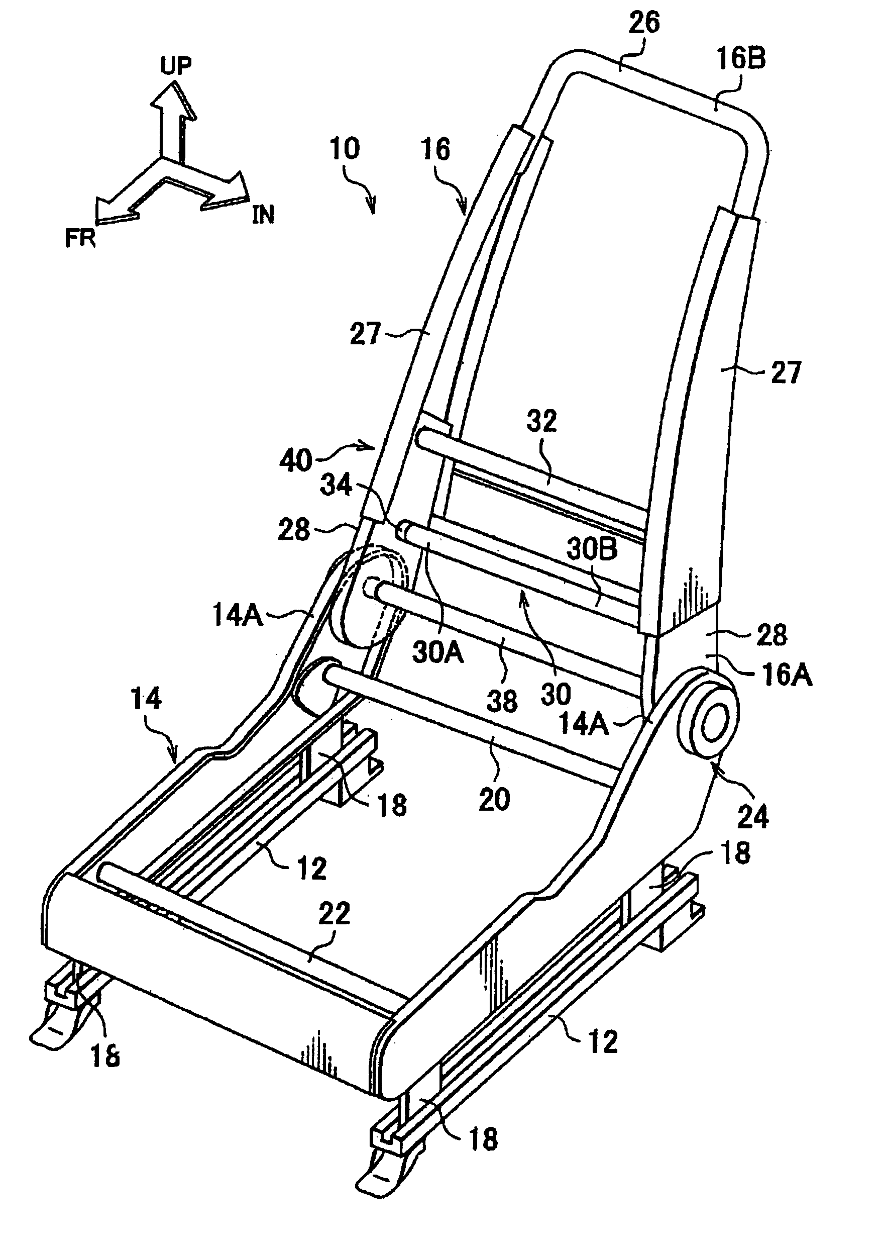
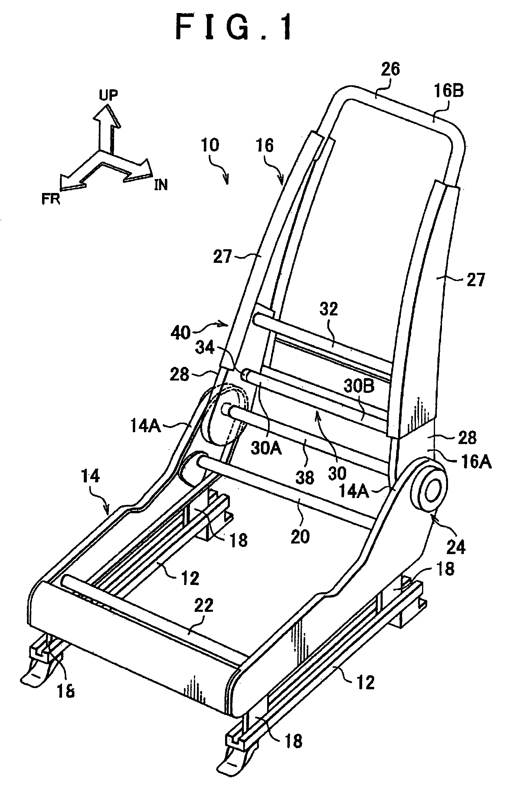
[0049]FIG. 1 is a perspective view of a seat frame of the vehicle seat 10 as viewed from the front. As shown in FIG. 1, the vehicle seat 10 is installed on a pair of rails 12 disposed longitudinally in the floor of the vehicle body. The vehicle seat 10 is equipped with a seat cushion frame 14 disposed along the longitudinal direction, and a seatback frame 16 functioning as a sub-frame disposed above a rear end of the seat cushion frame 14. The seat cushion frame 14 constitutes a seat cushion (not shown) for supporting the hips and thighs of a seated...

third embodiment

[0099](2) In the first, second, or third embodiment of the invention, the elastic body is provided at the end of the rod. However, a construction may also be adopted in which one, two, or more elastic bodies are provided at an intermediate portion of the rod. Thus, the level of minor vibrations of the vehicle seat in the minor displacement range may be reduced. Also, in the major displacement range, the elastic body at the intermediate portion is deformed to its limit, or the elastic bodies at the intermediate portion are deformed to their limits, and the end faces of the rod indirectly abut on each other. Thereby increasing the rigidity of the vehicle seat.

[0100](3) In the first embodiment of the invention, the two rods 30, 32 are provided. However, It would be better to state “the number of reinforcing rods is not restricted to two; instead any number of rods may be used as appropriate. Further, in the first, second, or third embodiment of the invention, the elastic body is provid...

sixth embodiment

[0101](4) In the fourth, fifth, or sixth embodiment of the invention, one end of the rod for reinforcement is provided with the clearance. However, a construction in which both the ends of the rod for reinforcement are joined to the sub-frame, and the intermediate portion of the rod is provided with a clearance may also be adopted, as shown in FIG. 19.

[0102](5) In the fourth, fifth, or sixth embodiment of the invention, the single rod for reinforcement is provided with the clearance. However, a construction in which a plurality of rods for reinforcement are provided with clearances respectively may also be adopted.

[0103](6) In each of the embodiments of the invention, the seatback frame is provided with the rods according to the invention along the width direction of the vehicle. However, the invention is not limited to this construction. For example, the rod according to the invention may be provided at an incline within the seat frame.

[0104](7) In each of the embodiments of the in...


PUM


Abstract

A vehicle seat (10) is equipped with a seat frame composed of a sub-frame (16) and a rod (30) provided between certain regions of the sub-frame. The rod is equipped with a minor vibration damping portion (34) that maintains rigidity of the seat frame when the seat frame is displaced by a large amount and suppresses an increase in rigidity of the seat frame when the seat frame is displaced by a small amount to reduce the level of minor vibrations in the vehicle seat.

Description

CROSS-REFERENCE TO RELATED APPLICATIONS[0001]This application is the U.S. National stage of PCT / IB2009 / 000295 filed on Feb. 19, 2009 which claims the benefit of JP2008-037502 filed on Feb. 19, 2008, both of which are hereby incorporated by reference.BACKGROUND OF THE INVENTION[0002]1. Field of the Invention[0003]The invention relates to a vehicle seat having a rod provided between certain regions of the seat frame.[0004]2. Description of the Related Art[0005]A seat having a vibration damping member hung across a seat frame constituting a seatback to reinforce the seat frame is described in Japanese Patent Application Publication No. 2001-211960 (JP-A-2001-211960). The resistance of the seat to vibrations is improved by reinforcing the seat frame.[0006]However, according to JP-A-2001-211960, the increased rigidity of the seat frame resulting from the vibration damping member suppresses minor displacement or minor deformation of the seat frame itself and thus increases the resonance f...

Claims


Application Information

Patent Timeline
Patent Type & Authority Patents(United States)
IPC IPC(8): B60N2/42B60N2/90B60N2/68
CPCB60N2/68B60N2205/20
Inventor ISHIMOTO, MANABUISHIZAKI, KEISUKE
Owner TOYOTA JIDOSHA KK
Why Eureka
Try Eureka