Soft tissue repair methods and apparatus
What is Al technical title?
Al technical title is built by PatSnap Al team. It summarizes the technical point description of the patent document.
a soft tissue and apparatus technology, applied in the field of soft tissue repair, can solve the problems of reducing the efficiency of disc degeneration surgery, so as to facilitate reconstruction, repair, and the closure of apertures, and prevent recurrent herniation
Inactive Publication Date: 2014-09-16
ANOVA
View PDF256 Cites 1 Cited by
Summary
Abstract
Description
Claims
Application Information
AI Technical Summary
This helps you quickly interpret patents by identifying the three key elements:
Problems solved by technology
Method used
Benefits of technology
[0012]The invention broadly facilitates reconstruction, repair, and the closure of apertures in soft tissues, including the anulus fibrosus (AF), heart, lung, abdomen, thorax, vascular structures and other organs. The invention may also be used in the treatment of herniated discs, annular tears of the disc, or disc degeneration, while enabling surgeons to preserve the contained nucleus pulposus. The methods and apparatus may be used to treat discs throughout the spine including the cervical, thoracic, and lumbar spines of humans and animals. Such reconstruction prevents recurrent herniation following microlumbar discectomy.
[0013]The invention also enables surgeons to reconstruct the anulus fibrosus and replace or augment the nucleus pulposus. Novel nucleus replacements (NR) may be added to the disc. Anulus reconstruction prevents extrusion of the nucleus replacements through holes in the anulus fibrosus. The nucleus replacements and the anulus fibrosus reconstruction prevent excessive pressure on the anulus fibrosus that may cause back or leg pain. The nucleus replacements may be made of natural or synthetic materials. Synthetic nucleus replacements may be made of, but are not limited to, polymers including polyurethane, silicon, hydrogel, or other elastomers.
[0014]Preferred embodiments of the invention include devices for positioning flexible longitudinal fixation components across apertures in the AF, heart, or other structure. One or more flexible longitudinal fixation components preferably pass across the inlet and the outlet of apertures. The inlets of the apertures are generally located closer to the central portions of the treated structures and generally are located further from patients' skin than the outlets of the apertures. The invention preferably closes the inlets and outlets of apertures, which facilitates full thickness healing of the soft tissue defect and provides a better seal of the defects. Sealing apertures is especially important in structures such as the heart and IVD to prevent leakage of blood and NP tissue, respectively. Tension on the flexible longitudinal fixation components preferably narrows or closes the apertures. Knotless fixation technologies such as suture welding are preferably used to fasten the ends of the flexible longitudinal fixation components.
Problems solved by technology
The nucleus becomes thinner and less able to handle compression loads.
The redundant annular fibers are less effective in controlling vertebral motion.
Current surgical treatments for disc degeneration are destructive.
The first two groups of procedures compromise the treated disc.
Fusion procedures transmit additional stress to the adjacent discs, which results in premature disc degeneration of the adjacent discs.
These destructive procedures lead to acceleration of disc degeneration.
Current nucleus replacements (NRs) may cause lower back pain if too much pressure is applied to the anulus fibrosus.
Compressed nerves cause back and leg or arm pain.
The opening in the anulus fibrosus is enlarged during surgery, further weakening the anulus fibrosus.
Although microlumbar discectomy decreases or eliminates a patient's leg or arm pain, the procedure damages weakened discs.
Method used
Image
Click on the blue label to locate the original text in one second.
Reading with bidirectional positioning of images and text.
Examples
Embodiment Construction
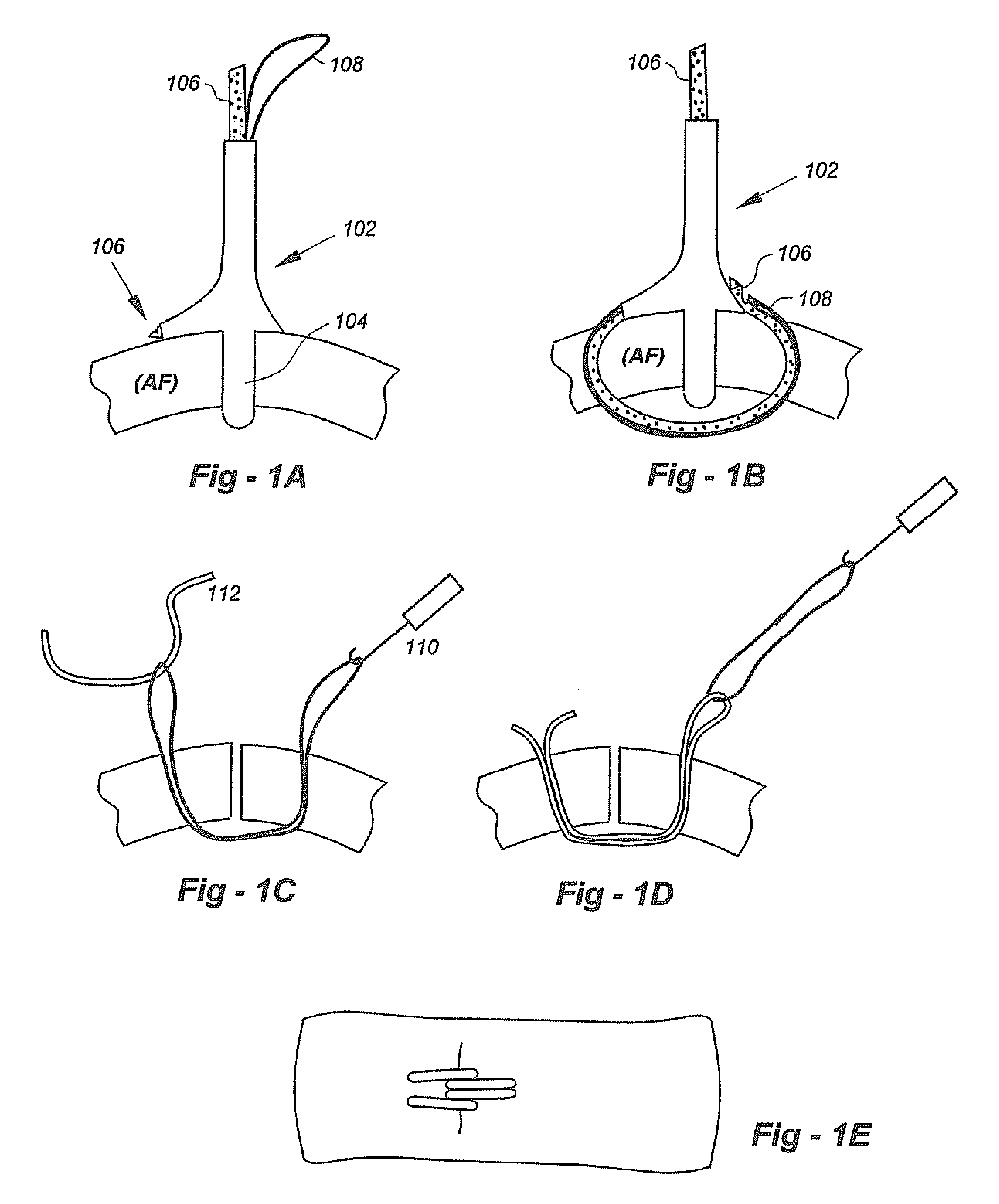
[0182]FIG. 1A is a lateral view of an alternative embodiment of the invention drawn in FIG. 15A of my co-pending patent application U.S. Ser. No. 61 / 300,993, the entire content of which is incorporated herein by reference, and a superior view of an axial cross section of a portion of the anulus fibrosus (AF). The distal end 104 of a cannulated instrument 102, which positions and stabilizes the instrument, is seen extending through an aperture in the AF. A needle 106 made of shape memory material, such as Nitinol, and a wire loop 108 pass through the cannulated instrument.
[0183]FIG. 1B is a lateral view of the embodiment of the invention drawn in FIG. 1A and a superior view of an axial cross section of a portion of the AF. The distal end of needle and one end of the wire loop were advanced through the cannulated instrument and the AF. The wire loop is captured in a hook-like feature in the needle. The painted end of the needle rides along a recess on the right side of the instrument....
PUM
Property
Measurement
Unit
angle
aaaaa
aaaaa
water content
aaaaa
aaaaa
water content
aaaaa
aaaaa
Abstract
Instruments and methods facilitate reconstruction, repair, and the closure of apertures in soft tissues, including the anulus fibrosus (AF), heart, lung, abdomen, thorax, vascular structures and other organs. Flexible longitudinal fixation components (i.e., sutures) are positioned across apertures in soft tissues, preferably to closes the inlets and / or outlets of such apertures. Tension on the flexible longitudinal fixation components may be used to narrow or close the apertures. Knotless fixation technologies such as suture welding are preferably used to fasten the ends of the flexible longitudinal fixation components. Certain embodiments include an intra-aperture component dimensioned for positioning within a defect in the AF, with one or more components being used to maintain the intra-aperture component in position. For example, the flexible longitudinal fixation component(s) may be anchored to one of the upper and lower vertebral bodies.
Description
REFERENCE TO RELATED APPLICATIONS[0001]This U.S. patent application claims priority from U.S. provisional patent application Ser. No. 61 / 305,683, filed Feb. 18, 2010 and U.S. provisional patent application Ser. No. 61 / 381,585, filed Sep. 10, 2010. This U.S. patent application is also a continuation-in-part of PCT / US2009 / 065954, filed Nov. 25, 2009, which is a Box VI priority application of U.S. provisional patent application 61 / 118,246, filed Nov. 26, 2008. This U.S. patent application is also a continuation-in-part of U.S. patent application Ser. No. 12 / 263,753, filed Nov. 3, 2008, which claims priority from U.S. provisional patent application Ser. No. 60 / 984,657, filed Nov. 1, 2007. This application is also a continuation-in-part of U.S. patent application Ser. No. 11 / 811,751, filed Jun. 12, 2007, which claims priority from U.S. provisional patent application Ser. No. 60 / 813,232, filed Jun. 13, 2006 and U.S. provisional patent application Ser. No. 60 / 847,649, filed Sep. 26, 2006. ...
Claims
Application Information
Patent Timeline
Application Date:The date an application was filed.
Publication Date:The date a patent or application was officially published.
First Publication Date:The earliest publication date of a patent with the same application number.
Issue Date:Publication date of the patent grant document.
PCT Entry Date:The Entry date of PCT National Phase.
Estimated Expiry Date:The statutory expiry date of a patent right according to the Patent Law, and it is the longest term of protection that the patent right can achieve without the termination of the patent right due to other reasons(Term extension factor has been taken into account ).
Invalid Date:Actual expiry date is based on effective date or publication date of legal transaction data of invalid patent.