
Intervertebral disc treatment methods and apparatus

a treatment method and technology for intervertebral discs, applied in the field of treatment of intervertebral disc herniation and degenerative disc disease, can solve the problems of reduced treatment effectiveness reduced treatment efficiency of disc degeneration surgery, so as to prevent recurrent herniation and facilitate reconstruction

Inactive Publication Date: 2014-07-01
ANOVA
View PDF257 Cites 2 Cited by
  • Summary
  • Abstract
  • Description
  • Claims
  • Application Information

AI Technical Summary

Benefits of technology

The invention is about a surgical technique that can help prevent a herniated disc after microlumbar discectomy and also treat herniated discs, anular tears of the disc, or disc degeneration. It involves reconstructing the anulus fibrosus and replacing or augmenting the nucleus pulposus. This technique helps to prevent excessive pressure on the anulus fibrosus and minimize back or leg pain. The nucleus replacements can be made of natural or synthetic materials, such as polymers like polyurethane or silicon. Overall, this invention can provide better outcomes for patients and animals with spinal disc disorders.

Problems solved by technology

The nucleus becomes thinner and less able to handle compression loads.
The redundant anular fibers are less effective in controlling vertebral motion.
Current surgical treatments for disc degeneration are destructive.
The first two groups of procedures compromise the treated disc.
Fusion procedures transmit additional stress to the adjacent discs, which results in premature disc degeneration of the adjacent discs.
These destructive procedures lead to acceleration of disc degeneration.
Current nucleus replacements (NRs) may cause lower back pain if too much pressure is applied to the anulus fibrosus.
Compressed nerves cause back and leg or arm pain.
The opening in the anulus fibrosus is enlarged during surgery, further weakening the anulus fibrosus.
Although microlumbar discectomy decreases or eliminates a patient's leg or arm pain, the procedure damages weakened discs.

Method used


Image

  • Intervertebral disc treatment methods and apparatus
  • Intervertebral disc treatment methods and apparatus
  • Intervertebral disc treatment methods and apparatus

Examples


Embodiment Construction

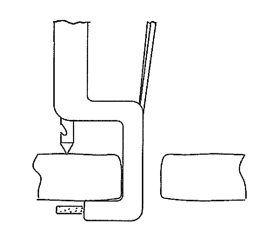
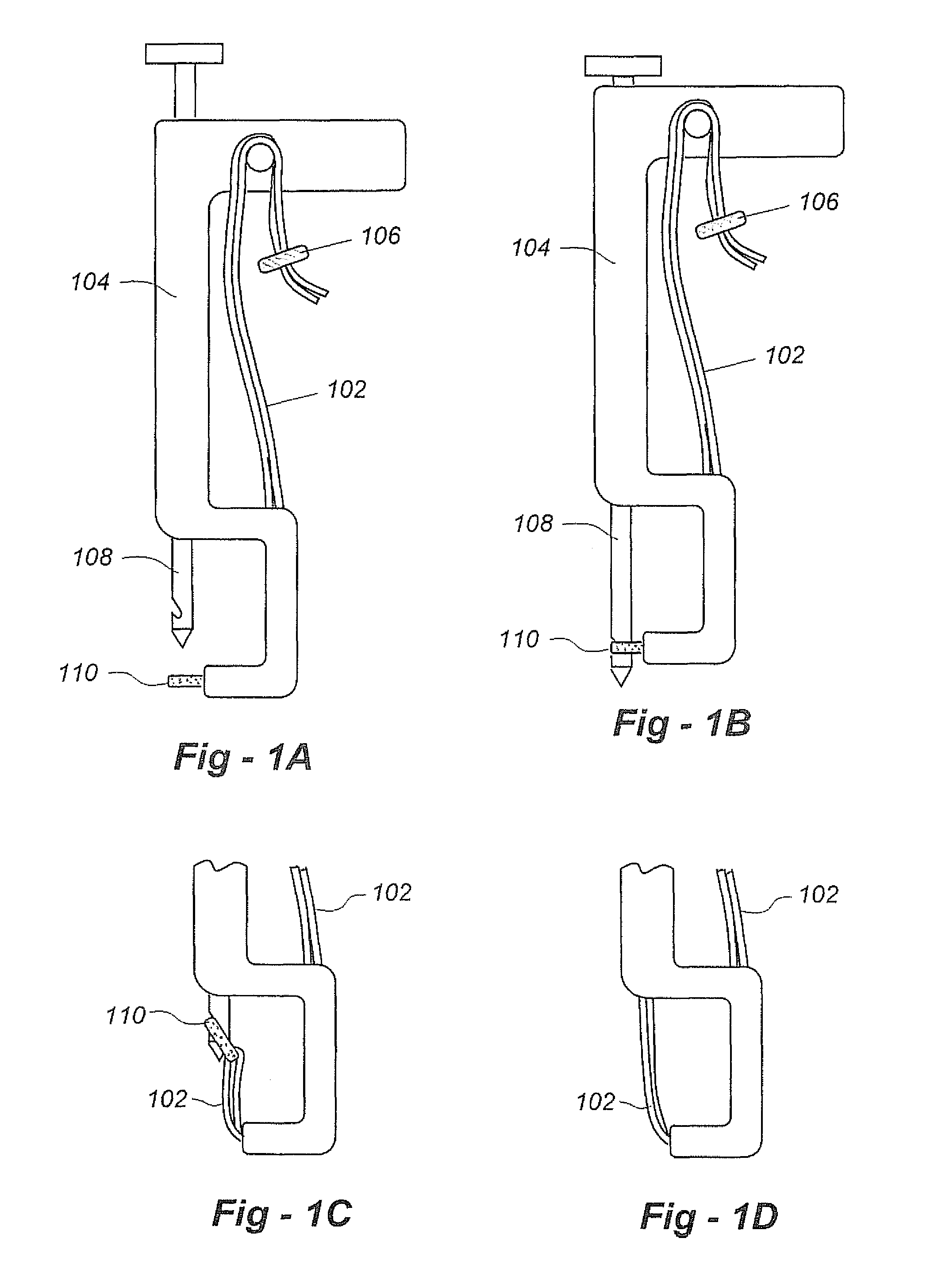
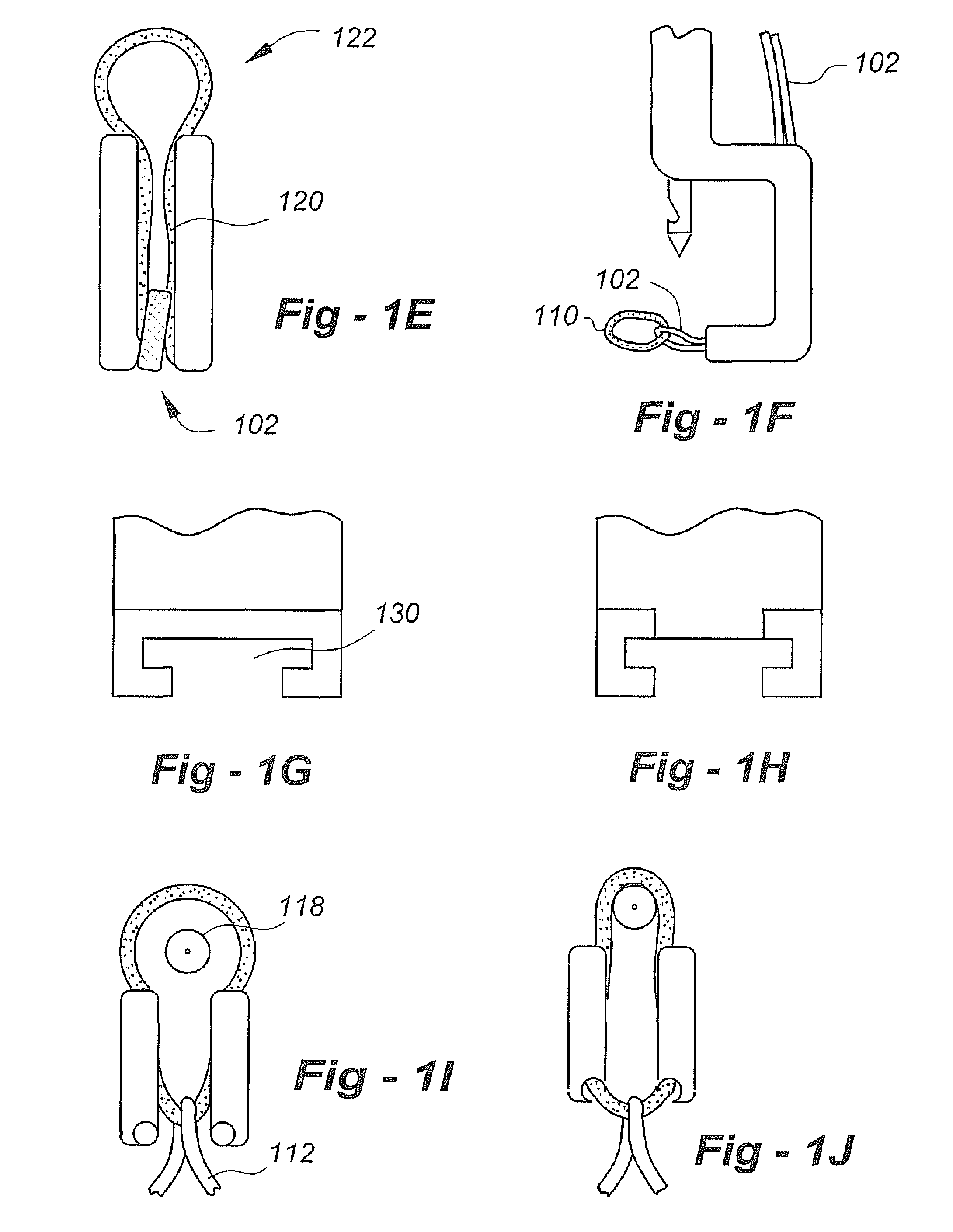
[0095]FIG. 1A is a lateral view of the preferred embodiment of the invention that may be used to pass the ends of the flexible longitudinal fixation component or the central portion of such flexible component through the AF. The Figure represents an alternative embodiment of FIG. 3A of my co-pending application PCT / US2009 / 065954, the entire content of which is incorporated herein by reference. The flexible longitudinal fixation component 102 is passed through a handle component 104. The handle component is pressed into a releasable fastening feature at the tip of the footplate at the distal end of the tool. The first and second arms of the flexible longitudinal fixation component also pass through a slot like opening on the bottom and posterior portions to the footplate of the instrument and wraps around a projection on the handle of the instrument. The first and second arms of the flexible longitudinal fixation component are then pressed into a releasable fastening feature on the h...


PUM


Abstract

Instrumentation and methods facilitate reconstruction of the anulus fibrosus (AF) and the nucleus pulposus (NP). An intra-aperture component is dimensioned for positioning within a defect in the AF, with one or more components being used to maintain the intra-aperture component in position. The intra-aperture component may be porous and flexible while being intentionally non-expandable in cross section following its positioning within the defect. A component used to maintain the intra-aperture component within the defect includes a flexible longitudinal fixation component that passes through the intra-aperture component and a region of the AF apart from the defect. If available, this may be a region of the AF having overlapping layers with intact fibers in different directions. The flexible longitudinal fixation component may be anchored to one of the upper and lower vertebral bodies.

Description

REFERENCE TO RELATED APPLICATIONS[0001]This U.S. patent application claims priority from U.S. provisional patent application Ser. No. 61 / 300,993, filed Feb. 3, 2010. This U.S. patent application is also a continuation-in-part of PCT / US2009 / 065954, filed Nov. 25, 2009, which is a Box VI priority application of U.S. provisional patent application 61 / 118,246, filed Nov. 26, 2008. This U.S. patent application is also a continuation-in-part of U.S. patent application Ser. No. 12 / 263,753, filed Nov. 3, 2008, which claims priority from U.S. provisional patent application Ser. No. 60 / 984,657, filed Nov. 1, 2007. This application is also a continuation-in-part of U.S. patent application Ser. No. 11 / 811,751, filed Jun. 12, 2007, which claims priority from U.S. provisional patent application Ser. No. 60 / 813,232, filed Jun. 13, 2006 and U.S. provisional patent application Ser. No. 60 / 847,649, filed Sep. 26, 2006. The entire content of each application is incorporated herein by reference.FIELD O...

Claims


Application Information

Patent Timeline
Patent Type & Authority Patents(United States)
IPC IPC(8): A61F2/44
CPCA61F2/44A61F2002/4435A61F2/4611A61F2220/0075A61F2002/30462A61F2002/444A61F2002/4627A61F2002/30092A61F2/442A61F2002/30579A61F2/4455
Inventor FERREE, BRET, A.
Owner ANOVA
Learn More