Method and system for object reconstruction

a technology of object reconstruction and object data, applied in the field of method and system for object reconstruction, can solve the problems of low 3-d resolution, inability to provide real-time mapping of objects, and the 3d information obtained usually contains only relatively sparse samples, and achieves simple and inexpensive optical setup and facilitates object reconstruction.

Active Publication Date: 2013-03-19
APPLE INC
View PDF154 Cites 55 Cited by
  • Summary
  • Abstract
  • Description
  • Claims
  • Application Information

AI Technical Summary

Benefits of technology

[0026]There is accordingly a need in the art to facilitate the object reconstruction, by providing a novel technique allowing a real-time and very accurate mapping of 3-D objects, which can be achieved with a very simple and inexpensive optical set up.
[0030]The main idea of the present invention consists of utilizing projection of a laser random speckle pattern onto an object the 3D surface data of which is to be reconstructed. Laser speckles are random self-generated patterns [15]. Preferably, the pattern is constant, but generally may be partitioned or other type varying along the Z axis (i.e. along the axis of speckle propagation). The term “constant speckle pattern” used herein signifies that the pattern is substantially not varying along the Z-axis within the region in which 3D measurements are to be taken. In addition, the depth of focus of such pattern is relatively large, e.g., order of several meters, or as required by a specific application, being controlled by changing the laser spot size on the diffuser and the laser wavelength. Hence, the use of a laser random pattern provides a large longitudinal range which can be mapped, and allows for significantly reducing both the optical complexity in designing a projection system and that of the post-processing, thus allowing for the real-time object reconstruction.
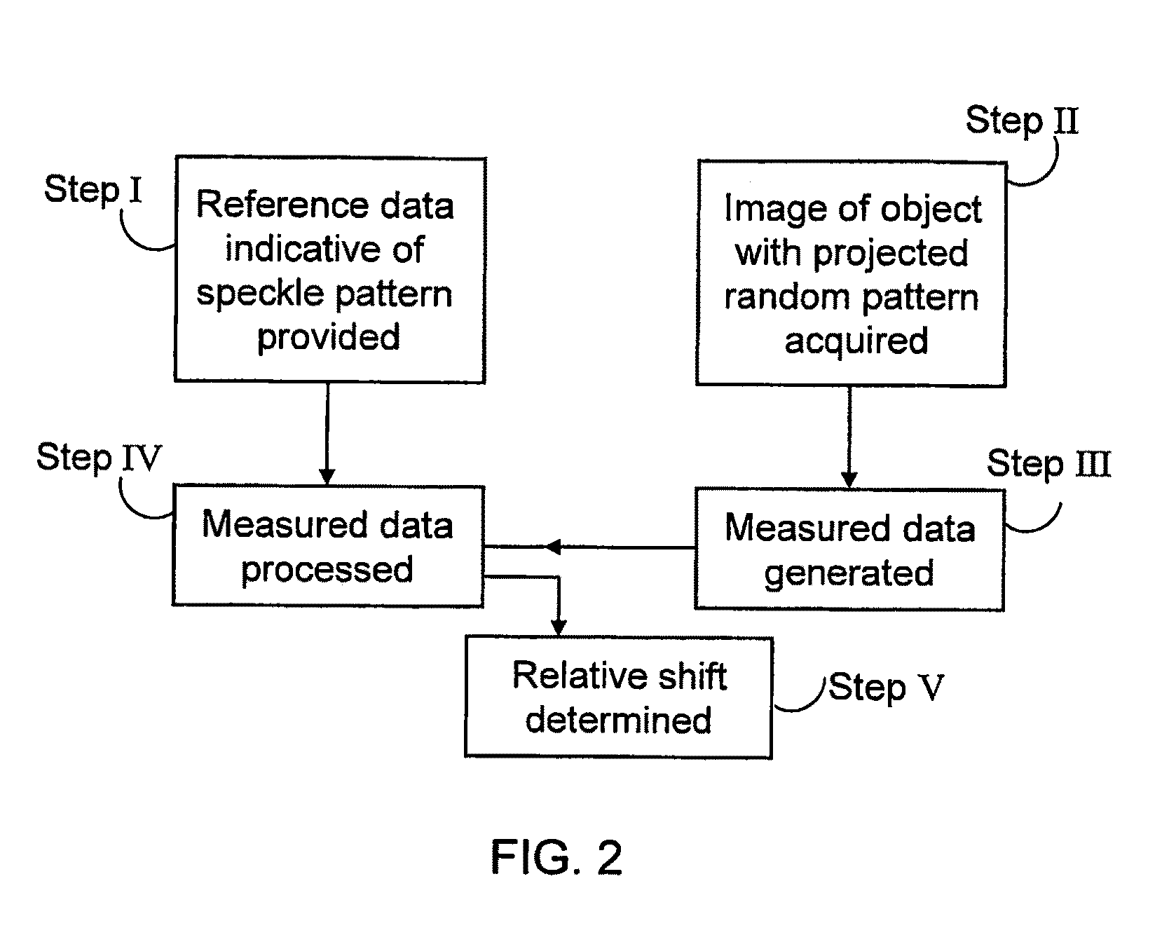
[0033]An optical set up (projection module) can be very simple and cheap: it can include only a small coherent light source (laser) and a pattern generator in the form of a light diffuser (e.g., piece of ground glass that diffuses light impinging thereon by addition of random phase), or e.g. in the form of a holographically recorded, randomized surface relief structure, which is accommodated in the optical path of laser light and scatters this light in the form of constant and random speckle pattern onto the object. It is important to note that the invention allows for acquiring only a single image of the object with a projected random pattern (the so-called single-snapshot solution) and for using a simple image matching algorithm, e.g. a correlation based image processing algorithm, which is thus of low computational complexity. Also, it is important, to note that the invention, even when utilizing more than one images, allows for operation with a single stationary mounted camera (generally, with the single field of view). These properties allow real time realization of the 3-D mapping.
[0035]Thus, according to one broad aspect of the invention, there is provided a system for use in the object reconstruction, the system comprising: an illuminating unit comprising a coherent light source and a generator of a random speckle pattern (e.g. diffuser unit) accommodated in the optical path of illuminating light propagating from the light source towards an object thus projecting onto the object a coherent random speckle pattern; and an imaging unit for detecting a light response of an illuminated region and generating image data, the image data being indicative of the object with the projected speckles pattern and thus indicative of a shift of the pattern in the image of the object relative to a reference image of said pattern, the system thereby enabling real-time reconstruction of a three-dimensional map of the object.
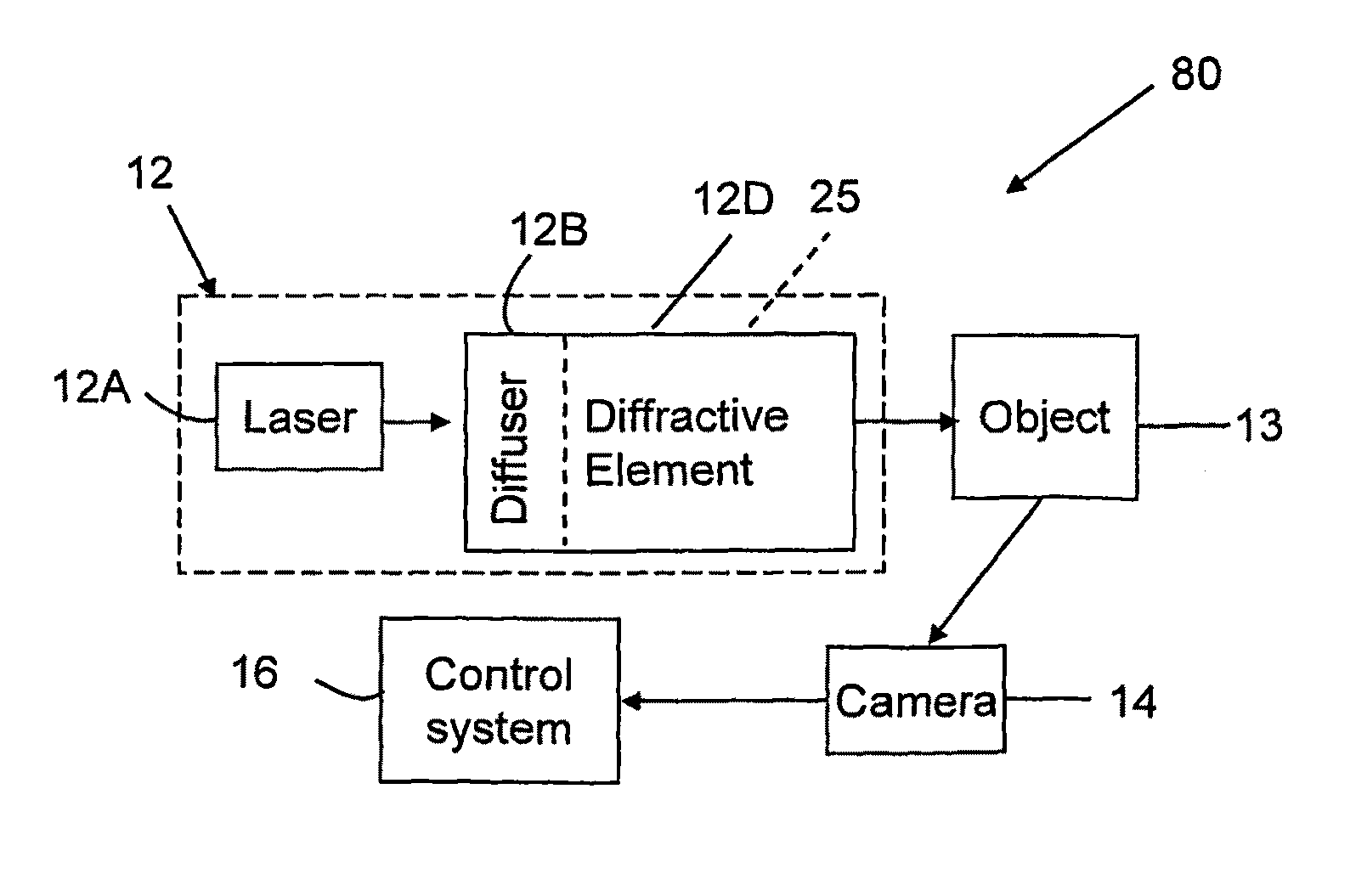
[0043]Preferably, the system includes an adjustor configured for reducing the illumination brightness variation between different regions of the field of view of the imaging unit. Such adjustor may include a diffractive optical element. The latter may be incorporated within or attached to the diffuser, or located in the optical path of illuminating light propagating towards the diffuser. The diffractive optical element operates together with the diffuser to adjust the brightness within a plane transversal to the optical path of illuminating light propagation.

Problems solved by technology

The main disadvantage of this approach is its low 3-D resolution, which strongly depends on a number of pixels in both cameras, the detail (e.g. texture) present on the scene, and a relative orientation of the cameras (angle and distance between them).
Moreover, this approach does not provide for real-time mapping of objects because the extraction of 3-D information requires high level processing operations such as classification and registration.
An additional problem with this approach is that 3D information obtained usually contains only relatively sparse samples of object depth.
This technique, however, requires high level processing, and is inaccurate since the shadow of edges is the noisiest region of the image.
Furthermore, this approach accumulates errors, since the first shadow is sued as a reference for the computation in the entire image.
This technique, however, does not provide a real time process of the object reconstruction; it takes time to scan the object with the line; and the estimation becomes more distorted in case the object moves.
These techniques are also not real-time since several projections are required.
In addition, in order to obtain good 3-D resolution very large and complicated codes are required; this makes a projection system very expensive and not practical.
Although with these techniques scanning is not required and the 3-D information can be obtained in real time, these technique suffer from the fact that 3-D information is wrapped since relative movements larger than the period of the projected pattern cannot be distinguished, and thus one cannot identify whether the obtained shift is that to be taken as is or an integer multiplied by the period size is to be added.
Another disadvantage of this approach is associated with the depth of focus of the projected pattern.
After a certain distance, the pattern is defocused, and it is very hard to extract numerically the relative shift of the periods.

Method used


Image

  • Method and system for object reconstruction
  • Method and system for object reconstruction
  • Method and system for object reconstruction

Examples


Embodiment Construction

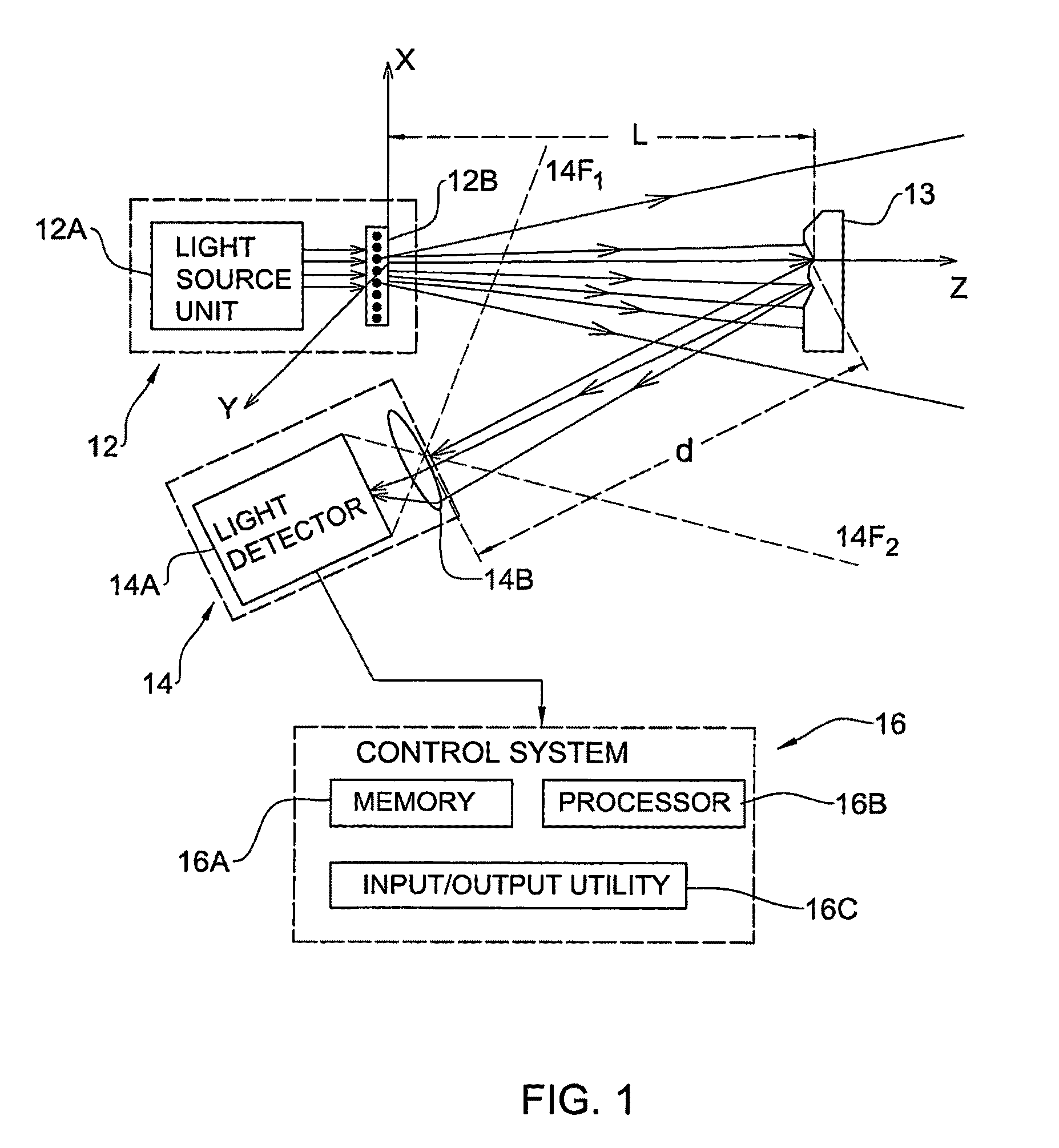
[0055]Referring to FIG. 1, there is schematically illustrated an example of a system 10 of the present invention for use in 3-D mapping of objects. System 10 is an optical mapping system including an illuminating unit 12 configured to project a random speckle pattern (preferably constant pattern) onto an object 13; and an imaging device 14.

[0056]Illuminating unit 12 includes a coherent light source 12A, and a generator 12B of a constant random speckle pattern accommodated in the optical path of illuminating light, preferably very close (e.g., up to a physical contact) to the light source output. Light source 12A may be constituted by a light emitting assembly (laser) and / or by a light guiding arrangement (e.g., optical fiber) associated with a remote light emitting assembly. Pattern generator 12B is a light diffuser, for example a ground glass.

[0057]Imaging device 14 includes alight detector 14A (a pixel matrix, e.g., CCD) equipped with an imaging lens arrangement 14B. The latter ma...


PUM


Abstract

A system and method are presented for use in the object reconstruction. The system comprises an illuminating unit, and an imaging unit (see FIG. 1). The illuminating unit comprises a coherent light source and a generator of a random speckle pattern accommodated in the optical path of illuminating light propagating from the light source towards an object, thereby projecting onto the object a coherent random speckle pattern. The imaging unit is configured for detecting a light response of an illuminated region and generating image data. The image data is indicative of the object with the projected speckles pattern and thus indicative of a shift of the pattern in the image of the object relative to a reference image of said pattern. This enables real-time reconstruction of a three-dimensional map of the object.

Description

REFERENCE TO CROSS-RELATED APPLICATIONS[0001]This application claims priority from U.S. provisional application No. 60 / 666,184, filed on Mar. 30, 2005, and from U.S. provisional application No. 60 / 724,903, filed on Oct. 11, 2005, herein incorporated by reference in its entirety.FIELD OF THE INVENTION[0002]This invention relates to a method and system for object reconstruction, enabling to extract highly resolved and real-time 3-D information.REFERENCES[0003]The following references are considered to be pertinent for the purpose of understanding the background of the present invention:[0004]1. S. Avidan and A. Shashua, “Trajectory triangulation: 3D reconstruction of moving points from amonocular image sequence,” PAMI, 22, 348-357 (2000).[0005]2. Y. G. Leclerc and A. F. Bobick, “The direct computation of height from shading,” CVPR, 552-558 (1991).[0006]3. R. Zhang and M. Shah, “Shape from intensity gradient,” SMC-A, 29, 318 (1999).[0007]4. R. Zhang and M. Shah, “Height recovery from i...

Claims


Application Information

Patent Timeline
Patent Type & Authority Patents(United States)
IPC IPC(8): H04N13/02G06T17/05
CPCG01B11/162H04N13/02G06T7/0057G01B11/2513G06T7/521H04N13/20H04N13/254G06T17/00G06T17/05H10B41/35H10B41/10G01B11/2441G06T2207/10012G06T2207/20056H01L23/528H01L23/535H01L29/0688H01L29/42328H01L29/788H01L2924/0002
Inventor ZALEVSKY, ZEEVSHPUNT, ALEXANDERMALZELS, AVIADGARCIA, JAVIER
Owner APPLE INC
Why Eureka
Try Eureka