Virtual image display device
a virtual image and display device technology, applied in the field of virtual image display devices, can solve the problems of difficult to respond to such requests, varied design limitations regarding the arrangement and size of the constituents of the device,
- Summary
- Abstract
- Description
- Claims
- Application Information
AI Technical Summary
Benefits of technology
Problems solved by technology
Method used
Image
Examples
second embodiment
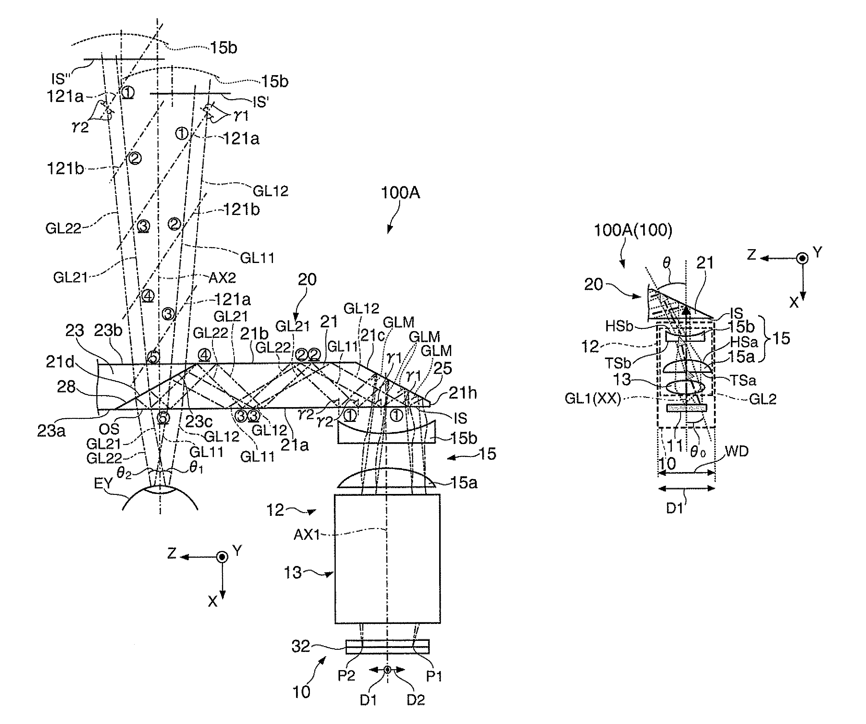
[0098]Hereinafter, a virtual image display device according to a second embodiment will be explained with reference to FIG. 10A and so on. It should be noted that the virtual image display device 200 according to the present embodiment is a modified example of the virtual image display device 100 according to the first embodiment, and it is assumed that the constituents denoted with the same reference numerals as those of the virtual display device 100 according to the first embodiment have substantially the same function unless particularly explained.
[0099]FIG. 10A is a cross-sectional view of the virtual image display device 200 viewed from the Y direction, and FIG. 10B is a side view of the virtual image display device 200 viewed from the Z direction. The virtual image display device 200 according to the present embodiment performs a contraction conversion in a aspect ratio conversion optical system 215 with respect to the second direction D2 (the Y direction) perpendicular to th...
third embodiment
[0104]Hereinafter, a virtual image display device according to a third embodiment will be explained with reference to FIG. 11A and so on. It should be noted that the virtual image display device 300 according to the present embodiment is a modified example of the virtual image display device 100 according to the first embodiment, and it is assumed that the constituents denoted with the same reference numerals as those of the virtual display device 100 according to the first embodiment have substantially the same function unless particularly explained.
[0105]The virtual image display device 300 performs both of the expansion conversion with respect to the first direction D1 (the Z direction) corresponding to the lateral direction for the observer, and the contraction conversion with respect to the second direction D2 (the Y direction) perpendicular to the first direction D1 as the aspect ratio conversion.
[0106]In order for performing the expansion conversion with respect to the first ...
fourth embodiment
[0110]Hereinafter, a virtual image display device according to a fourth embodiment will be explained with reference to FIG. 12A and so on. It should be noted that the virtual image display device 400 according to the present embodiment is a modified example of the virtual image display device 100 according to the first embodiment, and it is assumed that the constituents denoted with the same reference numerals as those of the virtual display device 100 according to the first embodiment have substantially the same function unless particularly explained.
[0111]As shown in FIG. 12A, the virtual image display device 400 is provided with an image processing section 430 in addition to the image forming device 10 and the light guide device 20.
[0112]The image processing section 430 performs the image processing on the image signal externally input to the image display device 11. Specifically, the image processing section 430 performs the necessary signal processing of the image signal, and a...
PUM
 Abstract
Description
Claims
Application Information
 - R&D
- Intellectual Property
- Life Sciences
- Materials
- Tech Scout
- Unparalleled Data Quality
- Higher Quality Content
- 60% Fewer Hallucinations
Browse by: Latest US Patents, China's latest patents, Technical Efficacy Thesaurus, Application Domain, Technology Topic, Popular Technical Reports.
© 2025 PatSnap. All rights reserved.Legal|Privacy policy|Modern Slavery Act Transparency Statement|Sitemap|About US| Contact US: help@patsnap.com


