Mounting structures for front pillar trims

a technology for mounting structures and pillars, which is applied in the direction of roofs, pedestrian/occupant safety arrangements, vehicular safety arrangements, etc., can solve the problems of not being able to form sufficient gaps, airbags not being smoothly inflated and developed, and the gap between the front pillar trim and the front pillar is not easily generated, so as to suppress local application of load, not easily interfere with the assist grip, and smooth inflated

Inactive Publication Date: 2014-09-23
HOWA MASCH LTD
View PDF14 Cites 5 Cited by
  • Summary
  • Abstract
  • Description
  • Claims
  • Application Information

AI Technical Summary

Benefits of technology

[0012]Thus, at the time of inflation of the airbag, the engagement mechanism is released, whereby the second front pillar trim can be easily detached from the first front pillar trim. At the time of inflation of the airbag, the first front pillar trim is retained by the front pillar together with the assist grip. However, the second front pillar trim has an opening, so that the second front pillar trim can be detached from the first front pillar trim with little or no interference from the first front pillar trim and the assist grip. As a result, the gap for expansion can assuredly be formed, enabling the airbag to be smoothly inflated.
[0013]At the time of inflation of the airbag, the second from pillar trim is detached from the first front pillar trim, and does not easily interfere with the assist grip. Thus, it is possible to suppress local application of a load to the front pillar trim due to the expansion pressure of the airbag. Thus, it is possible to suppress breakage of the front pillar trim.

Problems solved by technology

Accordingly, at the time of development of the airbag, the gap between the front pillar trim and the front pillar is not easily generated, and there is a fear of the airbag not being smoothly inflated and developed.
However, the assist grip is fastened to the front pillar that is a rigid body, so that the front pillar trim can only move to a position where it is in contact with the inner peripheral surface of the assist grip.
Thus, a sufficient gap is not formed between the front pillar and the front pillar trim, and there is a fear that the airbag won't smoothly inflate and form.
Depending on an order in which the easy-to-rupture portion is ruptured, a force is locally applied to the front pillar trim due to the expansion pressure of the airbag, and there is a fear of the front pillar trim being broken and scattered.
However, adding the cover involves an increase in cost.

Method used


Image

  • Mounting structures for front pillar trims
  • Mounting structures for front pillar trims
  • Mounting structures for front pillar trims

Examples


Embodiment Construction

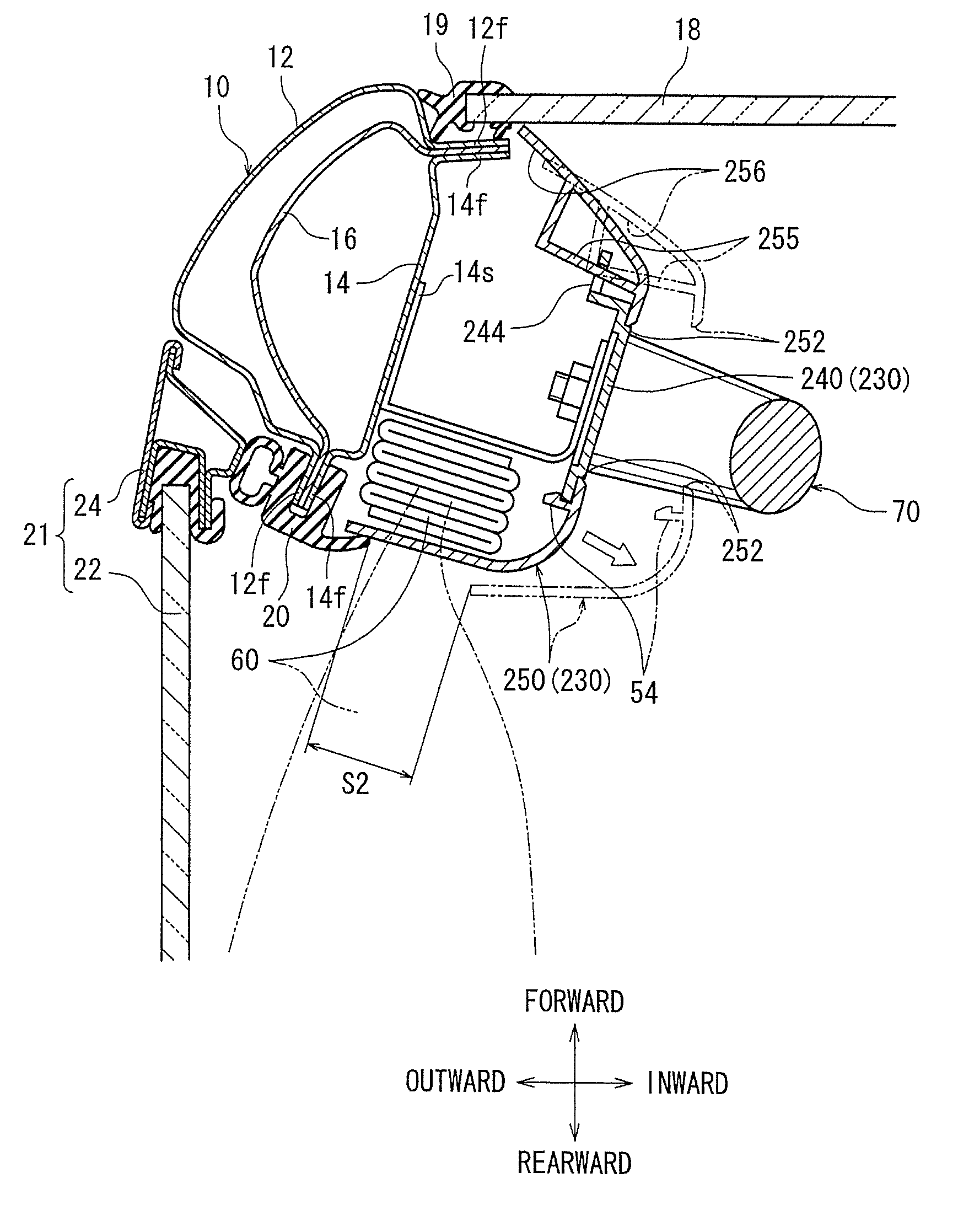
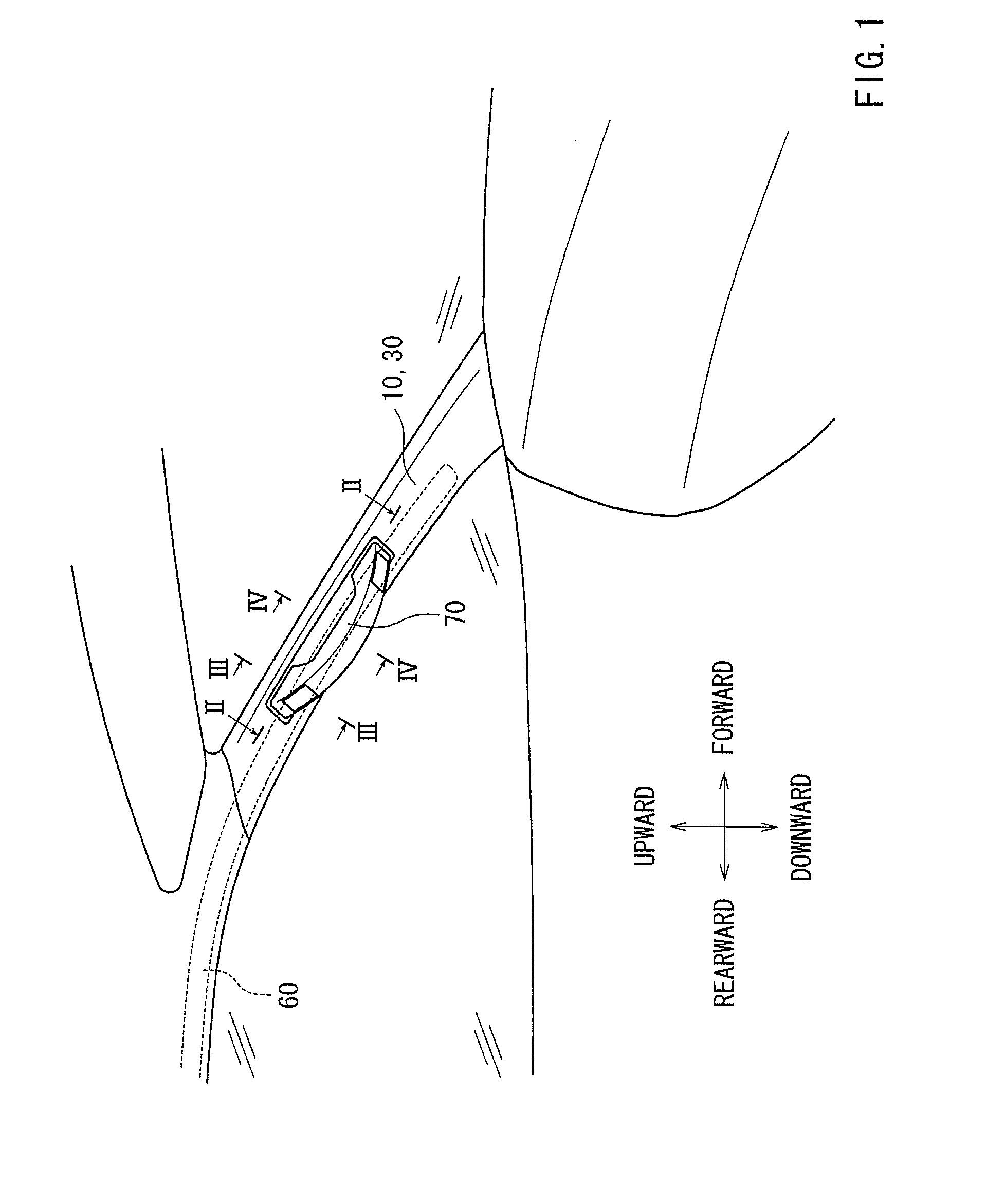
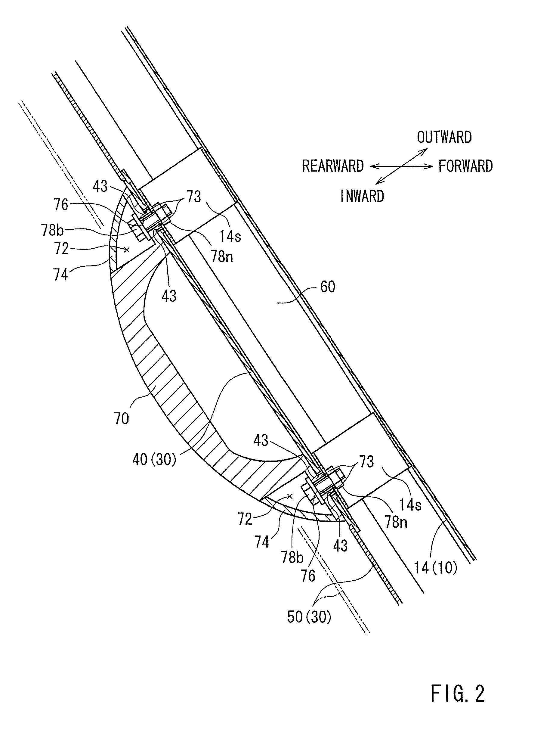
[0025]An embodiment will be described with reference to FIGS. 1 to 4. The front pillar trim mounting structure shown in FIG. 1 has a front pillar 10, a front pillar trim 30, an airbag 60, and an assist grip 70. As shown in FIGS. 1 and 3, the front pillar 10 is arranged between a main body and a roof panel of a vehicle. Among the pillars supporting the roof panel, the front pillar 10 is situated in the front portion of the vehicle. The front pillar trim 30 covers a vehicle inner side of the front pillar 10. The airbag 60 is located between the front pillar 10 and the front pillar trim 30. The assist grip 70 is attached to the front pillar 10, and extends in a longitudinal direction of a vehicle inner side surface of the front pillar trim 30.

[0026]As shown in FIGS. 3 and 4, the front pillar 10 has an outer panel 12, an inner panel 14 and a metal reinforcement 16. The outer panel 12 is formed of a steel plate, and constitutes an outer wall of the vehicle. The inner panel 14 is formed o...


PUM


Abstract

A front pillar trim mounting structure has a front pillar (10), a front pillar trim (30), an airbag (60), and an assist grip (70). The front pillar is provided in the front portion of a vehicle. The front pillar trim (30) covers the front pillar (10) from the inner side of the vehicle. The airbag (60) is located between the front pillar (10) and the front pillar trim (30). The assist grip (70) is attached to the front pillar (10), and is installed on a vehicle inner surface of the front pillar trim (30). The front pillar trim (30) has a first front pillar trim (40), a second front pillar trim (50), and an engagement mechanism (54). The assist grip (70) is installed on the first front pillar trim (40). The second front pillar trim (50) is provided with an opening where the first front pillar trim (40) is installed. The engagement mechanism (54) detachably connects the second front pillar trim (50) to first front pillar trim (40). The engagement mechanism (54) is configured to allow the second front pillar trim (50) to move with respect to the front pillar (10) by releasing the second front pillar trim (50) by an expansion pressure of the airbag (60) at a time of inflation of the airbag (60), so that a gap for deployment of the airbag (60) is formed between the second front pillar trim (50) and the front pillar (10).

Description

BACKGROUND[0001]1. Technical Field[0002]Embodiments of the present invention relate to a mounting structure for a front pillar trim accommodating an airbag and having an assist grip.[0003]2. Description of Related Art[0004]A vehicle main body includes side walls (e.g., doors and body side panels), a roof panel arranged above the side walls, and pillars supporting the roof panel. The pillars include a front pillar situated in a front portion of the vehicle. Since the major portion of the front pillar is formed of a metal plate-like member (e.g., a steel plate), a front pillar trim covering the vehicle inner side of the front pillar is provided. The front pillar trim constitutes the inner wall of the vehicle interior, and, like other trim members, is formed through a combination of an appropriate synthetic resin material, a textile material, etc. Thus, the front pillar trim has a design function of forming the vehicle inner wall as a smooth surface and a function of protecting an occu...

Claims


Application Information

Patent Timeline
Patent Type & Authority Patents(United States)
IPC IPC(8): B60R21/213B60R13/02B60N3/02B60R21/215
CPCB60R21/213B60N3/026B60R13/025B60R2021/21518
Inventor MASATSUGU, TOSHIKATSUSETO, HIROYUKINARIKIYO, TAKAHIRO
Owner HOWA MASCH LTD
Why Eureka
Try Eureka