
Image processing device, display device and non-transitory computer readable recording medium

a display device and image processing technology, applied in the direction of digital output to print units, instruments, digital computers, etc., can solve the problems of poor operation efficiency, waste of image data already generated by reading documents, and conventional image processing devices are not capable of allowing users to see wha

Active Publication Date: 2014-09-23
KONICA MINOLTA INC
View PDF12 Cites 0 Cited by
  • Summary
  • Abstract
  • Description
  • Claims
  • Application Information

AI Technical Summary

Benefits of technology

[0015]The present invention is intended to solve the above problems. Thus, the present invention is intended to provide an image processing device, a display device and a non-transitory computer readable recording medium capable of allowing a user to check how an image changes in response to image processing performed during execution of a job, and setting a continuous displaying time of each image based on the user's intention to display the image that changes during execution of the job, thereby allowing the user to fully check the change in the image especially the one that he or she would like to check.
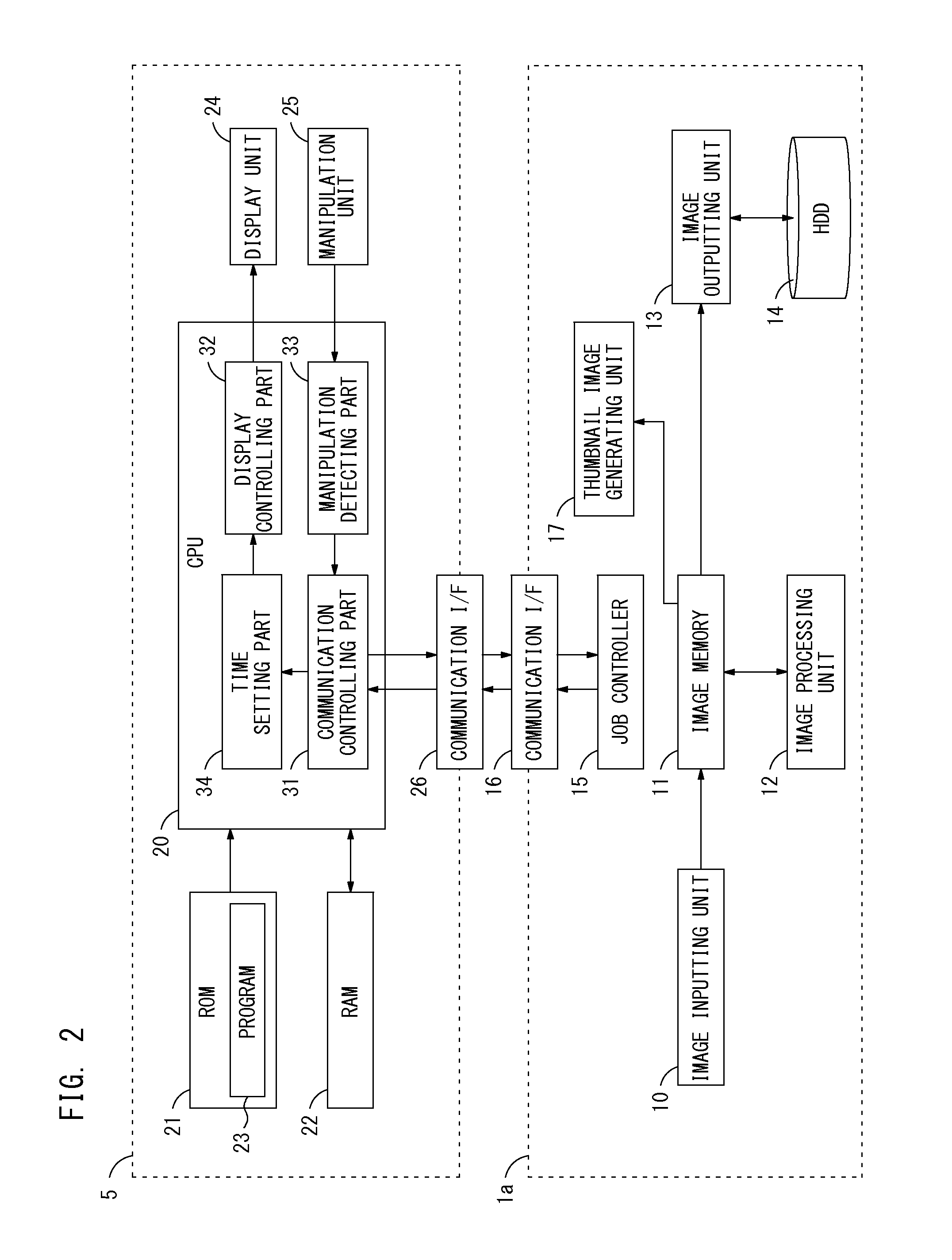
[0020]Third, the present invention is directed to a non-transitory computer readable recording medium on which a program is recorded. The program is executable on a display device including a display part on which a variety of information is displayed and a manipulation detecting part for detecting an operation on the display part. The program is executed on the display device, thereby causing the display device to display in cooperation with an image processing device capable of performing a variety of image processing to process image data.

Problems solved by technology

In such cases, according to the above-described known techniques, the settings of each image processing performed during execution of the job are not allowed to be changed in the middle of the process.
In this case, the image data already generated by reading the document would be wasted.
Also for the user, he or she has to place again the document already read once on the scanner section when again giving the instruction on execution of the job, resulting in poor operation efficiency.
It is supposed that the reason why the user cannot notice a mistake on the settings before completion of execution of the job is that the conventional image processing devices are not capable of allowing the user to see what processing on the image data is performed during execution of the job on a real-time basis.
The conventional image processing devices are not capable of showing how the image data changes in response to the series of the image processing performed during execution of the job to the user on the real-time basis.
Therefore, the user often notices that the settings of the image processing are not configured as intended by checking the output image after the execution of the job is complete.
The execution of the job would be wasted.
Even when how the image data has changed in response to each image processing is displayed sequentially before the image output is started, a continuous displaying time to display each image becomes short so that the user is not allowed to fully check the detail of each image.

Method used


Image

  • Image processing device, display device and non-transitory computer readable recording medium
  • Image processing device, display device and non-transitory computer readable recording medium
  • Image processing device, display device and non-transitory computer readable recording medium

Examples


first preferred embodiment

(First Preferred Embodiment)

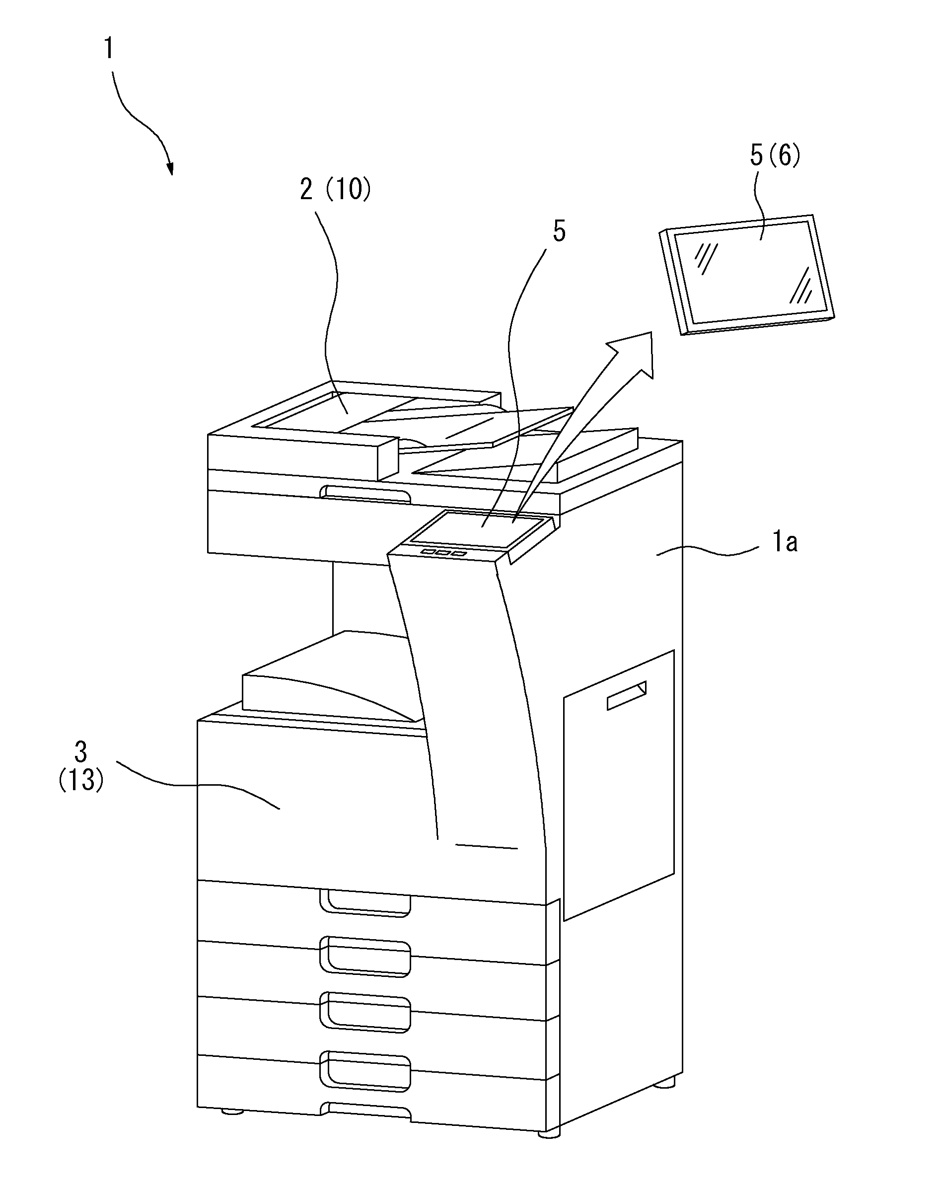
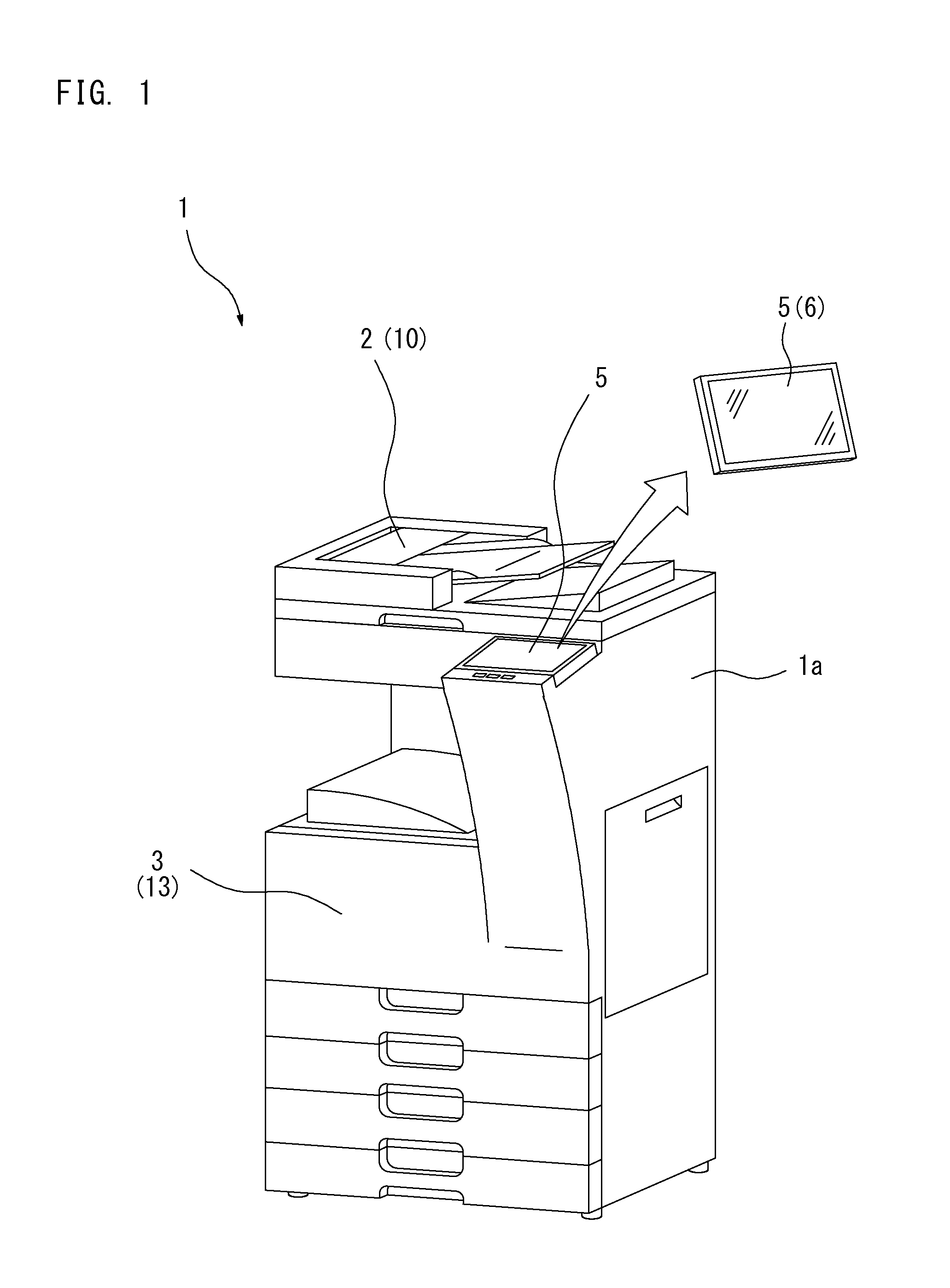
[0042]FIG. 1 shows an exemplary configuration of an image processing device I of the first preferred embodiment. The image processing device 1 is formed from a device such as one of MFPs capable of executing a variety of jobs including copy jobs, print jobs, scan jobs and fax jobs.

[0043]A device body 1a of the image processing device 1 includes a scanner section 2 and a printer section 3. The scanner section 2 is driven to read a document and generate image data thereof. The printer section 3 is driven to produce a printed output by forming an image on a sheet such as a printing sheet. The device body 1a is provided with an operational panel 5, a user interface operable by a user in use of the image processing device 1, on its front side. The operational panel 5 can be attached and removed from the device body 1a. For using the operational panel 5 by removing from the device body 1a, the operational panel 5 serves as a portable display device 6 such as a ...

second preferred embodiment

(Second Preferred Embodiment)

[0115]A second preferred embodiment is described next. In the first preferred embodiment as described above, each processing part, the background removing part 41, the resolution converting part 42, the color converting part 43, the sharpening part 44 and the overlaying part 45, of the image processing unit 12 is formed from the hardware. Each aforementioned processing part of the image processing unit 12 of the second preferred embodiment is formed from the software. In the second preferred embodiment, the configuration of the image processing device 1 is the same as that of first preferred embodiment.

[0116]When each processing part, the background removing part 41, the resolution converting part 42, the color converting part 43, the sharpening part 44 and the overlaying part 45, of the image processing unit 12 is formed from the software, the image processing unit 12 generally performs each image processing at a slower speed than the process speed for ...


PUM


Abstract

An image processing device, comprises: a display part on which a variety of information is displayed; an image processing part for performing a plurality of image processing sequentially to process an input image data; a thumbnail image generating part for generating a thumbnail image one after the other based on the input image data or the processed image data generated sequentially in response to each image processing performed by the image processing part; an image outputting part for outputting an image based on the image data which is processed through the entire plurality of image processing; a display controlling part for displaying a processing path of the plurality of image processing performed sequentially by the image processing part from the image data is input until the image is output on the display part, and for displaying the thumbnail image along the processing path.

Description

[0001]This application is based on the application No. 2012-168047 filed in Japan, the contents of which are hereby incorporated by reference.BACKGROUND OF THE INVENTION[0002]1. Field of the Invention[0003]The present invention relates to an image processing device, a display device and a non-transitory computer readable recording medium.[0004]2. Description of the Background Art[0005]For executing jobs, image processing devices such as MFPs perform a series of operations. The series of operations include an operation to perform a plurality of image processing set in advance to process input image data sequentially, to generate image data for output, and to output the generated image data for output. For a fax transmission job, for instance, the image processing device performs the plurality of image processing sequentially to process image data generated by reading a document by a scanner section and generates fax transmittable image data. The image processing device then sends the...

Claims


Application Information

Patent Timeline
Patent Type & Authority Patents(United States)
IPC IPC(8): G06F15/00G06K1/00H04N1/00G06F3/0481
CPCG06F3/0481H04N1/00413H04N1/00477H04N1/00949H04N1/00954
Inventor TORIYAMA, HIDEYUKI
Owner KONICA MINOLTA INC
Learn More