Wireless receiver

a receiver and wireless technology, applied in the field of wireless receivers, can solve the problem of 5 db of noise improvement achievable with a very low circuit power penalty, and achieve the effect of reducing noise requirements and low circuit power penalties

Active Publication Date: 2014-09-30
CASCODA
View PDF22 Cites 12 Cited by
  • Summary
  • Abstract
  • Description
  • Claims
  • Application Information

AI Technical Summary

Benefits of technology

[0020]The post-correlation approach to frequency correction allows designs according to the invention to be implemented with simple hardware compared to approaches which require intervention prior to the correlator. Simple receiver topology and a semi-coherent demodulator, should deliver near theoretical limits of SNRmin. Hence an improvement of around 5 dB over the existing non-coherent architectures is possible. Therefore, the receiver circuits can be designed from high gain active components with relatively relaxed noise requirements. Furthermore, the demodulator is in the digital circuit domain, such that the 5 dB of noise improvement is achievable with a very low circuit power penalty.
[0021]Embodiments of the invention can be realized with a signal resolution of ≦4 bits, resulting in a loss of less than 0.5 dB compared with 8 bit signal resolution. There is no need for phase and frequency compensation to be carried out before the correlation, as in the prior art, since the phase and frequency compensation is done based on the correlation values computed by the correlation unit. The use of timing extraction after correlation based on the maximum of the correlation values allows for a continuous optimization of signal amplitude.
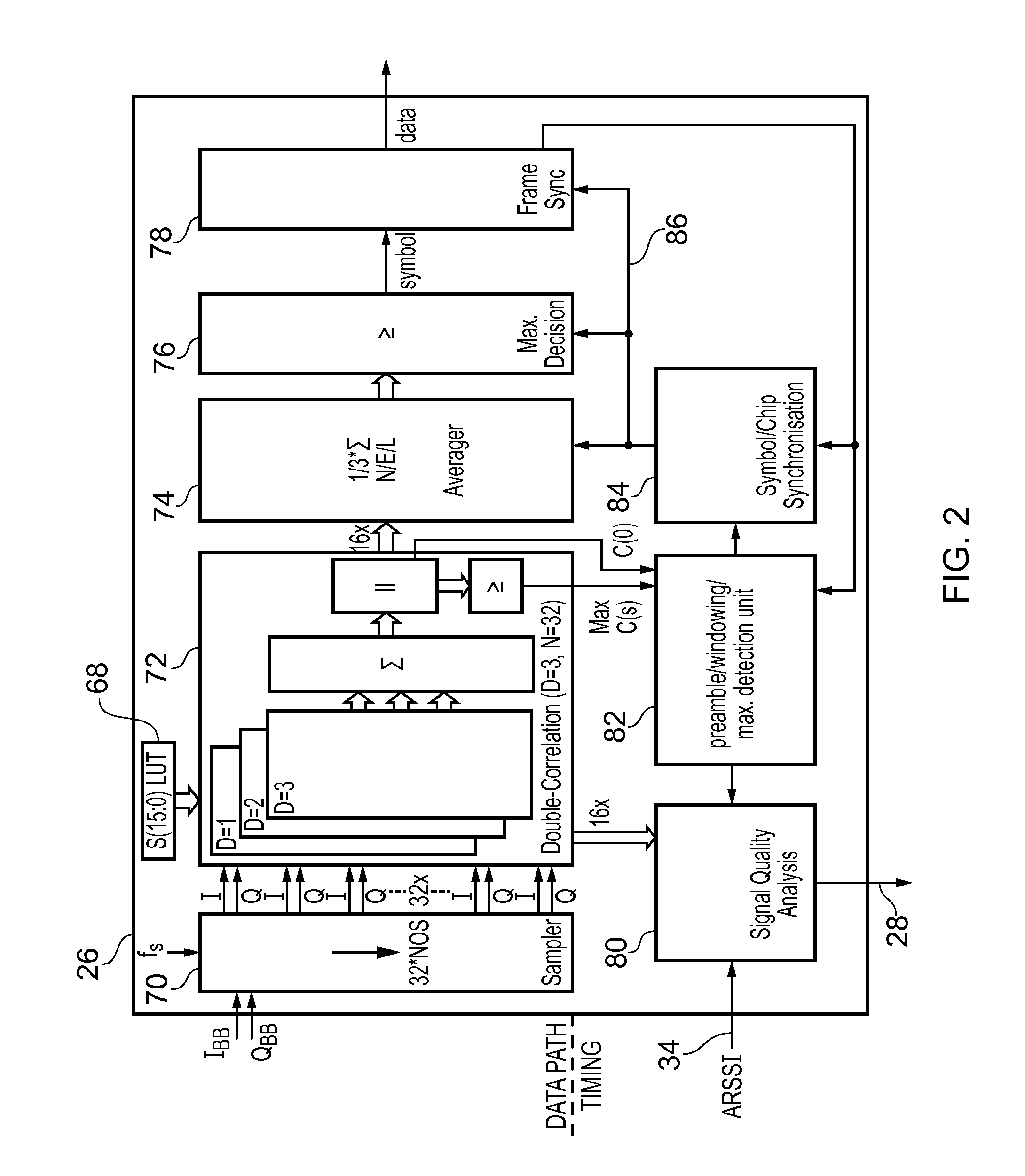
[0024]The digital decoder may further comprise an averaging unit interposed between the correlation unit and the symbol selection unit, the averaging unit being operable to modify the correlation values output by the correlation unit by averaging each correlation value over a succession of time intervals spanning a timing window centered around a predicted correct detection time. Averaging each correlation value over a succession of time intervals in this way, before determining which symbol is received, can provide an improvement in noise performance of around 3 dB.
[0027]Signal quality analysis based on a combination of analog received signal strength indication (ARSSI), correlation values and timing information, allows for the optimization the IF amplification chain by controlling the gain of one or more amplifiers present in the chain. A dynamic reduction in receiver power consumption is achieved if the input signal quality is more than sufficient to conform to the standard.

Problems solved by technology

Furthermore, the demodulator is in the digital circuit domain, such that the 5 dB of noise improvement is achievable with a very low circuit power penalty.

Method used


Image

  • Wireless receiver
  • Wireless receiver
  • Wireless receiver

Examples


first embodiment

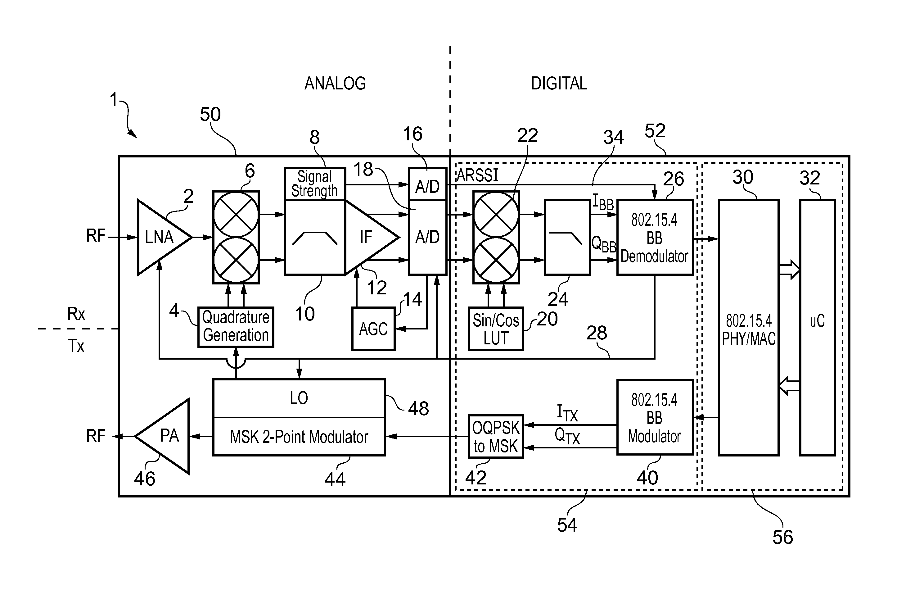
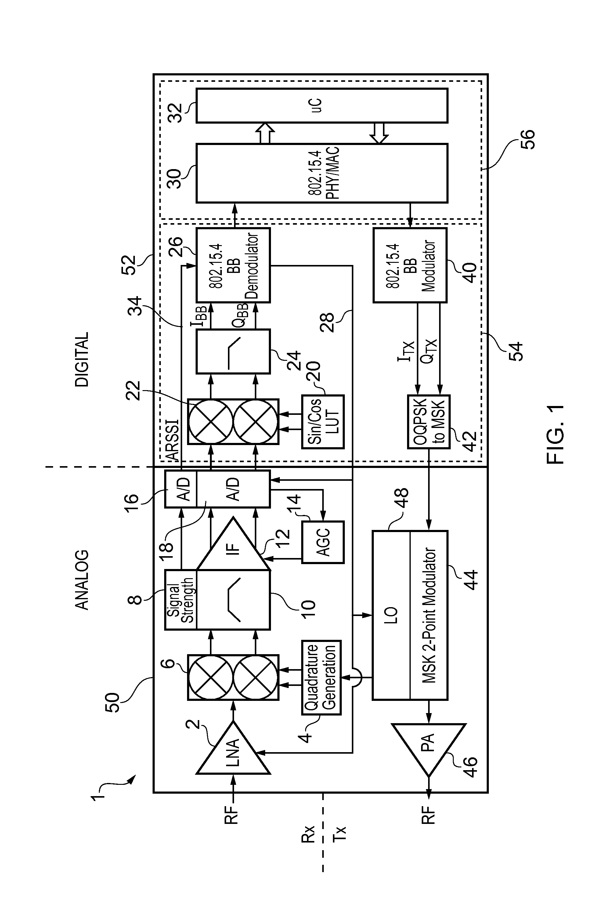
[0052]FIG. 1 shows a transceiver 1 according to the invention. The transceiver 1 shown in the figure is an integrated system. The only required external components are an antenna, an oscillator crystal and a power supply decoupler. That is to say the transceiver may be implemented on one chip, i.e. in a single integrated circuit. However, it will be appreciated that although desirable for cost reasons, a single chip solution is not a technical necessity.

[0053]The transceiver 1 has a functional split into two parts, namely a receiver Rx and a transmitter Tx, as well as a hardware split into two parts, namely an analog unit 50 and a digital unit 52. The analog unit 50 provides a radio frequency (RF) front end for the transmitter and receiver. The digital unit 52 comprises a digital baseband (BB) processor 54 and a system control unit 56. Referring to FIG. 1, the receiver components 2, 6, 10, 12, 18, 22, 24, and 26 are arranged in the upper part of the drawing with the signal path from...

second embodiment

[0128]FIG. 6 shows a transceiver 1 with an alternative system architecture according to the invention.

[0129]The architecture of the second embodiment has many common features with that of the first embodiment and the overall structure will be apparent by comparing FIG. 6 with FIG. 1. The same reference numerals are used in FIG. 6 as in FIG. 1 for components which are the same, or have a correspondence in terms of their high level function.

[0130]The transceiver 1 has a functional split into two parts, namely a receiver Rx and a transmitter Tx, as well as a hardware split into two parts, namely an analog unit 50 and a digital unit 52. The analog unit 50 provides an RF front end for the transmitter and receiver. The digital unit 52 comprises a digital baseband processor 54 and a system control unit 56. Referring to FIG. 6, the receiver components 2, 90, 92, 88, 18 and 26 are arranged in the upper part of the drawing with the signal path from left to right, and the transmitter component...


PUM


Abstract

A wireless receiver designed to conform to the standard IEEE 802.15.4. The receiver comprises an analog front-end and a digital decoder. The analog components of the front end include one or more amplifiers and an analog-to-digital converter (ADC). The digital decoder receives the output of the ADC and demodulates it in a demodulator which is driven at an a chip frequency by an internal or external clock. The demodulator comprises a sampler operable to sample the digital signal at a sampling frequency and a correlation unit operable to process a set of bits, referred to as a chip code, in the sampled digitized signal and output therefrom a set of correlation values. The set of correlation values is an indicator of likely mapping between the chip code that has been processed and a set of possible chip codes defined according to the standard. The demodulator further comprises a symbol selection unit and a frequency correction unit. The symbol selection unit has the function of deciding which symbol has been received based on an analysis of each set of correlation values. The frequency correction unit is operable to make adjustments to the chip frequency based on the correlation values output from the correlation unit, specifically to increase or decrease the chip frequency based on a measurement of whether the maximum correlation value among each set of correlation values occurs earlier or later than predicted. This scheme has the advantage that phase and frequency compensation is done after correlation avoiding the need for coherent demodulation while at the same time not requiring the stringent specifications of a conventional non-coherent demodulation scheme.

Description

[0001]This application claims the benefit of the filing date of U.S. Provisional Application No. 61 / 233,516 filed Aug. 13, 2009, which is incorporated herein by reference.BACKGROUND OF THE INVENTION[0002]The present invention relates to a wireless receiver, in particular as part of a wireless transceiver.[0003]There is an increasing need for energy efficient homes, offices and industrial plants. Energy efficiencies can be achieved through the deployment of wireless sensor network (WSN) systems, which allow for building automation, industrial monitoring and many other applications. To address this market, the 2.4 GHz IEEE 802.15.4 worldwide wireless standard has been defined, which specifies a short-range low-power wireless protocol. To conform to the standard, electronic devices will need to be developed which integrate radio-frequency (RF) electronic components, micro-controllers, on-chip sensors and sensor interfaces. For commercial reasons, this integration will need to be done o...

Claims


Application Information

Patent Timeline
Patent Type & Authority Patents(United States)
IPC IPC(8): H04B1/18H04J1/16H04L7/00H04B1/40
CPCH04B1/40
Inventor BRUCHNER, WOLFGANG
Owner CASCODA
Why Eureka
Try Eureka