Al technical title is built by PatSnap Al team. It summarizes the technical point description of the patent document.
a receiver and wireless technology, applied in the direction of pulse automatic control, radio transmission, electrical equipment, etc., can solve the problem of achieving 5 db of noise improvement with a very low circuit power penalty
Active Publication Date: 2011-02-17
CASCODA
View PDF17 Cites 38 Cited by
Summary
Abstract
Description
Claims
Application Information
AI Technical Summary
This helps you quickly interpret patents by identifying the three key elements:
Problems solved by technology
Method used
Benefits of technology
Problems solved by technology
Furthermore, the demodulator is in the digital circuit domain, such that the
Method used
Image
Click on the blue label to locate the original text in one second.
Reading with bidirectional positioning of images and text.
Examples
first embodiment
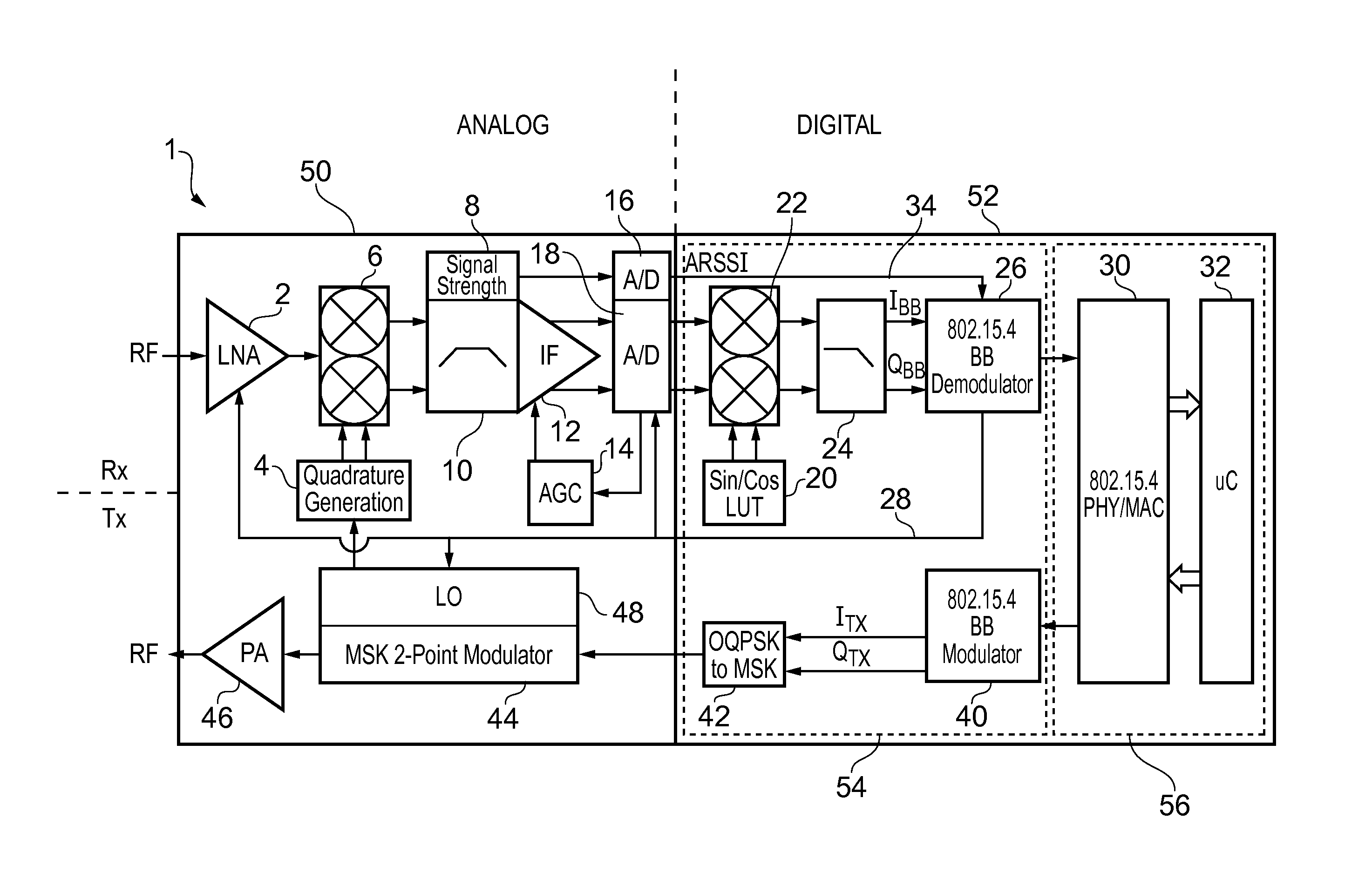
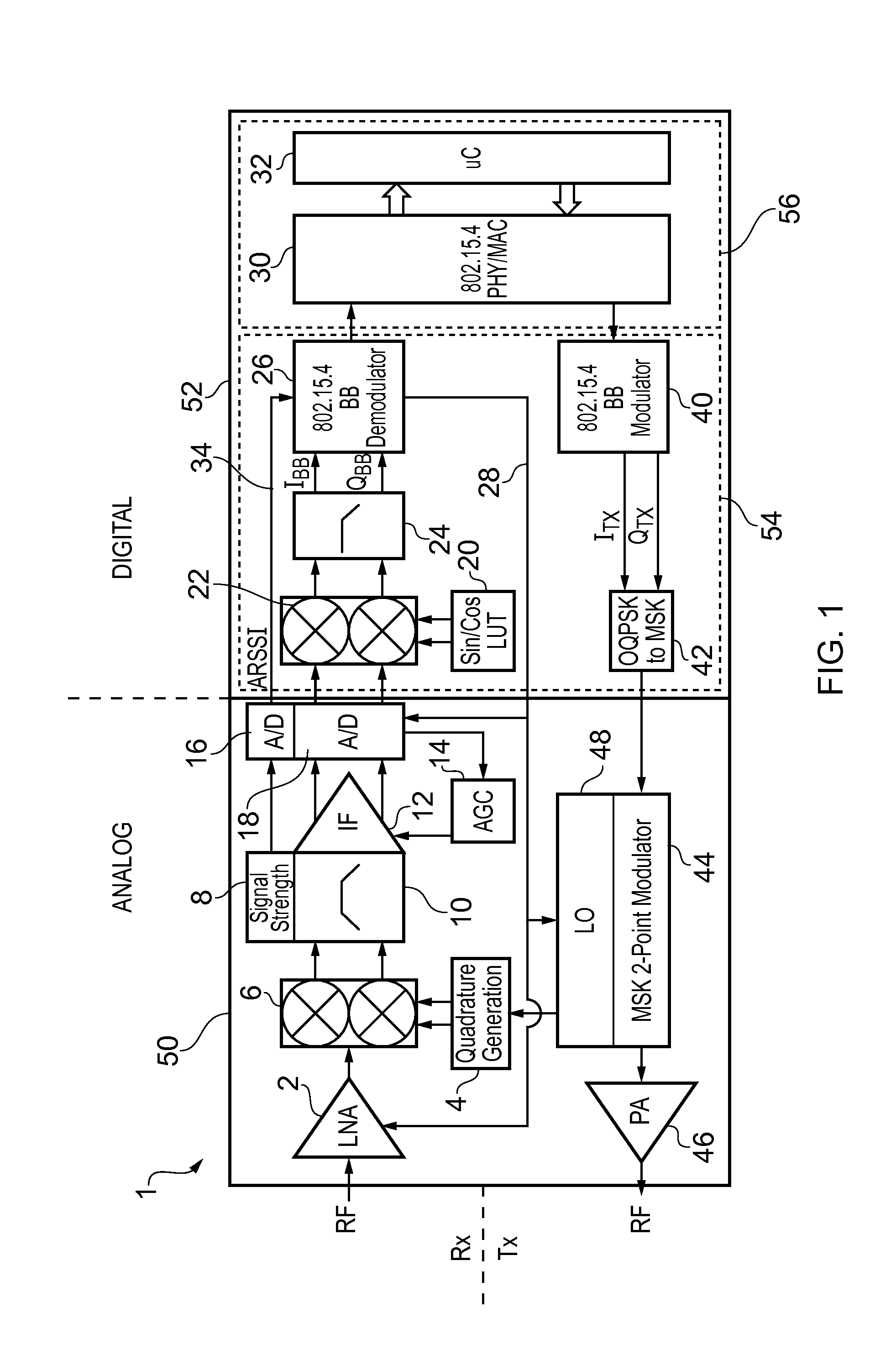
FIG. 1 shows a transceiver 1 according to the invention. The transceiver 1 shown in the figure is an integrated system. The only required external components are an antenna, an oscillator crystal and a power supply decoupler. That is to say the transceiver may be implemented on one chip, i.e. in a single integrated circuit. However, it will be appreciated that although desirable for cost reasons, a single chip solution is not a technical necessity.
The transceiver 1 has a functional split into two parts, namely a receiver Rx and a transmitter Tx, as well as a hardware split into two parts, namely an analog unit 50 and a digital unit 52. The analog unit 50 provides a radio frequency (RF) front end for the transmitter and receiver. The digital unit 52 comprises a digital baseband (BB) processor 54 and a system control unit 56. Referring to FIG. 1, the receiver components 2, 6, 10, 12, 18, 22, 24, and 26 are arranged in the upper part of the drawing with the signal path from left to rig...
second embodiment
FIG. 6 shows a transceiver 1 with an alternative system architecture according to the invention.
The architecture of the second embodiment has many common features with that of the first embodiment and the overall structure will be apparent by comparing FIG. 6 with FIG. 1. The same reference numerals are used in FIG. 6 as in FIG. 1 for components which are the same, or have a correspondence in terms of their high level function.
The transceiver 1 has a functional split into two parts, namely a receiver Rx and a transmitter Tx, as well as a hardware split into two parts, namely an analog unit 50 and a digital unit 52. The analog unit 50 provides an RF front end for the transmitter and receiver. The digital unit 52 comprises a digital baseband processor 54 and a system control unit 56. Referring to FIG. 6, the receiver components 2, 90, 92, 88, 18 and 26 are arranged in the upper part of the drawing with the signal path from left to right, and the transmitter components 46, 104, 102, 10...
PUM
Abstract
A wireless receiver designed to conform to the standard IEEE 802.15.4. The receiver comprises an analog front-end and a digital decoder. The analog components of the front end include one or more amplifiers and an analog-to-digital converter (ADC). The digital decoder receives the output of the ADC and demodulates it in a demodulator which is driven at an a chip frequency by an internal or external clock. The demodulator comprises a sampler operable to sample the digital signal at a sampling frequency and a correlation unit operable to process a set of bits, referred to as a chip code, in the sampled digitized signal and output therefrom a set of correlation values. The set of correlation values is an indicator of likely mapping between the chip code that has been processed and a set of possible chip codes defined according to the standard. The demodulator further comprises a symbol selection unit and a frequency correction unit. The symbol selection unit has the function of deciding which symbol has been received based on an analysis of each set of correlation values. The frequency correction unit is operable to make adjustments to the chip frequency based on the correlation values output from the correlation unit, specifically to increase or decrease the chip frequency based on a measurement of whether the maximum correlation value among each set of correlation values occurs earlier or later than predicted. This scheme has the advantage that phase and frequency compensation is done after correlation avoiding the need for coherent demodulation while at the same time not requiring the stringent specifications of a conventional non-coherent demodulation scheme.
Description
BACKGROUND OF THE INVENTIONThe present invention relates to a wireless receiver, in particular as part of a wireless transceiver.There is an increasing need for energy efficient homes, offices and industrial plants. Energy efficiencies can be achieved through the deployment of wireless sensor network (WSN) systems, which allow for building automation, industrial monitoring and many other applications. To address this market, the 2.4 GHz IEEE 802.15.4 worldwide wireless standard has been defined, which specifies a short-range low-power wireless protocol. To conform to the standard, electronic devices will need to be developed which integrate radio-frequency (RF) electronic components, micro-controllers, on-chip sensors and sensor interfaces. For commercial reasons, this integration will need to be done on a single integrated circuit, i.e. on a single chip.A wireless or radio transceiver conforming to IEEE 802.15.4 should utilize its transmitted power resource to maintain a satisfacto...
Claims
Application Information
Patent Timeline
Application Date:The date an application was filed.
Publication Date:The date a patent or application was officially published.
First Publication Date:The earliest publication date of a patent with the same application number.
Issue Date:Publication date of the patent grant document.
PCT Entry Date:The Entry date of PCT National Phase.
Estimated Expiry Date:The statutory expiry date of a patent right according to the Patent Law, and it is the longest term of protection that the patent right can achieve without the termination of the patent right due to other reasons(Term extension factor has been taken into account ).
Invalid Date:Actual expiry date is based on effective date or publication date of legal transaction data of invalid patent.