Dosing cap for container

a technology of dosing cap and container, which is applied in the direction of instruments, movable measuring chambers, single-unit apparatuses, etc., can solve the problems of reproducibility of fixed volume, inability to vary the volume dispensed by the end user, and loss or separation of measuring containers from liquid containers

Inactive Publication Date: 2014-10-07
CONOPCO INC D B A UNILEVER
View PDF23 Cites 15 Cited by
  • Summary
  • Abstract
  • Description
  • Claims
  • Application Information

AI Technical Summary

Benefits of technology

[0011]In a preferred embodiment, the seal permits flow of liquid from the inlet-side to the outlet-side provided there is a sufficient pressure difference across it. This is highly counter-intuitive because, on first consideration, it would seem to be contrary to the aim of controlling or fixing the quantity of liquid dispensed. The inventors have found that, surprisingly this does not prevent fixed quantities of liquid from being dispensed and in fact provides for a mechanically simple arrangement which is robust.
[0018]Once the pressure on the inlet-side is removed following dispensing the seal can begin to move from the second position towards the first position by action of the biasing means. This will have the initial effect of reducing the pressure on the outlet-side liquid volume (for not all of the outlet-side liquid volume is dispensed). This results in liquid flowing from the inlet-side liquid volume past the seal into the outlet-side liquid volume in response to the pressure difference. This flow acts to rebalance the pressure differences, allowing the biasing means to overcome the reduced pressure difference and continue to move the seal to its first position.
[0026]The liquid outlet seal means is another essential element of the invention. This acts to prevent flow out of the liquid outlet when the seal is in its second position. In a preferred embodiment, this is established by surrounding the outlet or otherwise covering it. In a further preferred embodiment, this is established by the liquid outlet seal means comprising a region which forms a seal around the outlet with a defined thickness.
[0027]In this way, further increases in pressure applied merely act to press the outlet seal more strongly, thus making the seal stronger. Thus, no liquid can leave the outlet by squeezing done when the seal is in its second position.
[0029]Another essential element of the invention is the dispensable liquid volume adjustment means. This allows a user to adjust the volume of liquid that is dispensed, so that the fixed volume dispensed can be increased or decreased as desired by the user.

Problems solved by technology

However, this solution, although simple, suffers from the danger of the measuring container becoming lost or separated from the liquid container.
However, combining this flexibility with the reproducibility of a fixed volume presents a particular challenge.
However, the volume dispensed cannot be varied by the end user and remains fixed.

Method used


Image

  • Dosing cap for container
  • Dosing cap for container
  • Dosing cap for container

Examples


Embodiment Construction

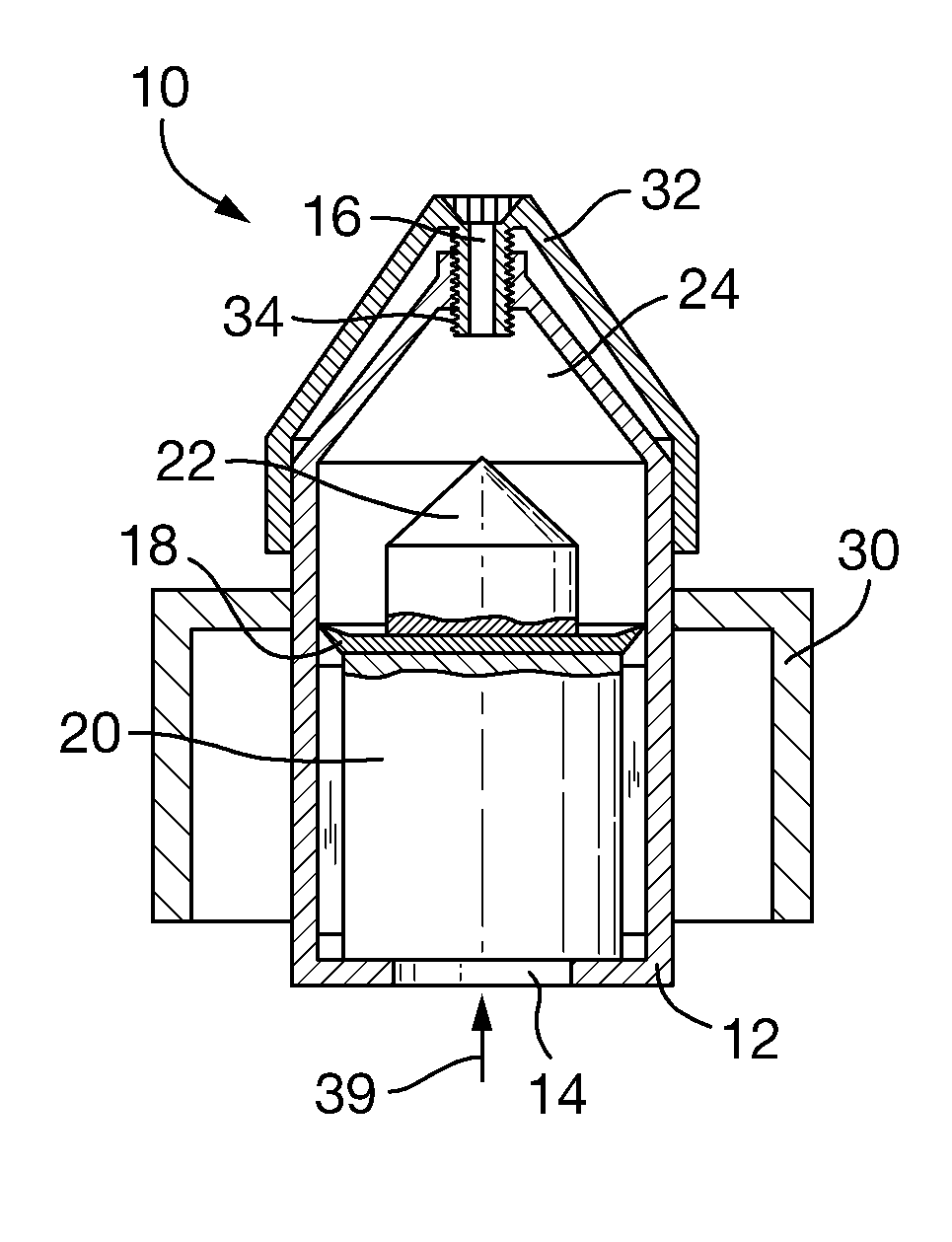
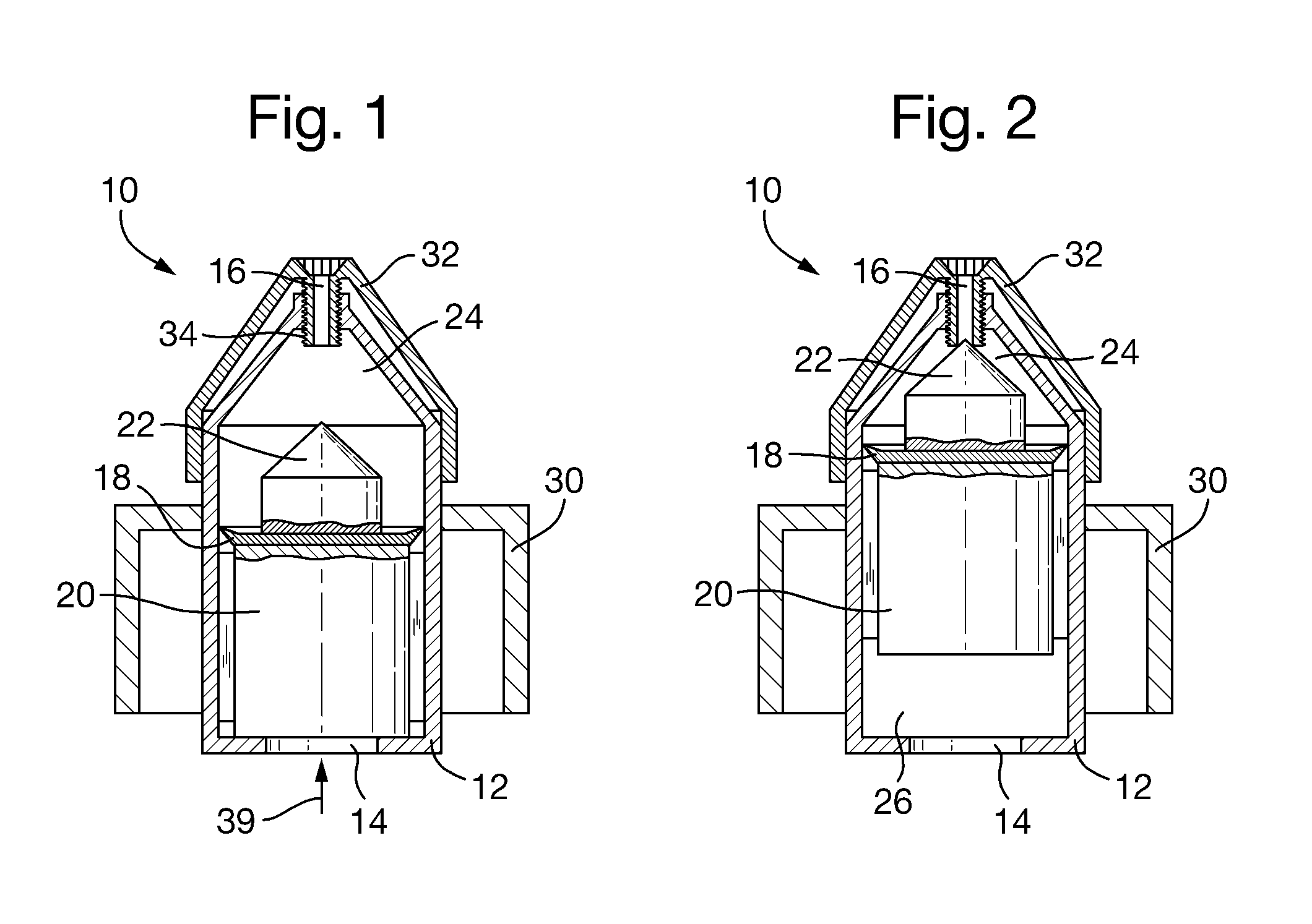
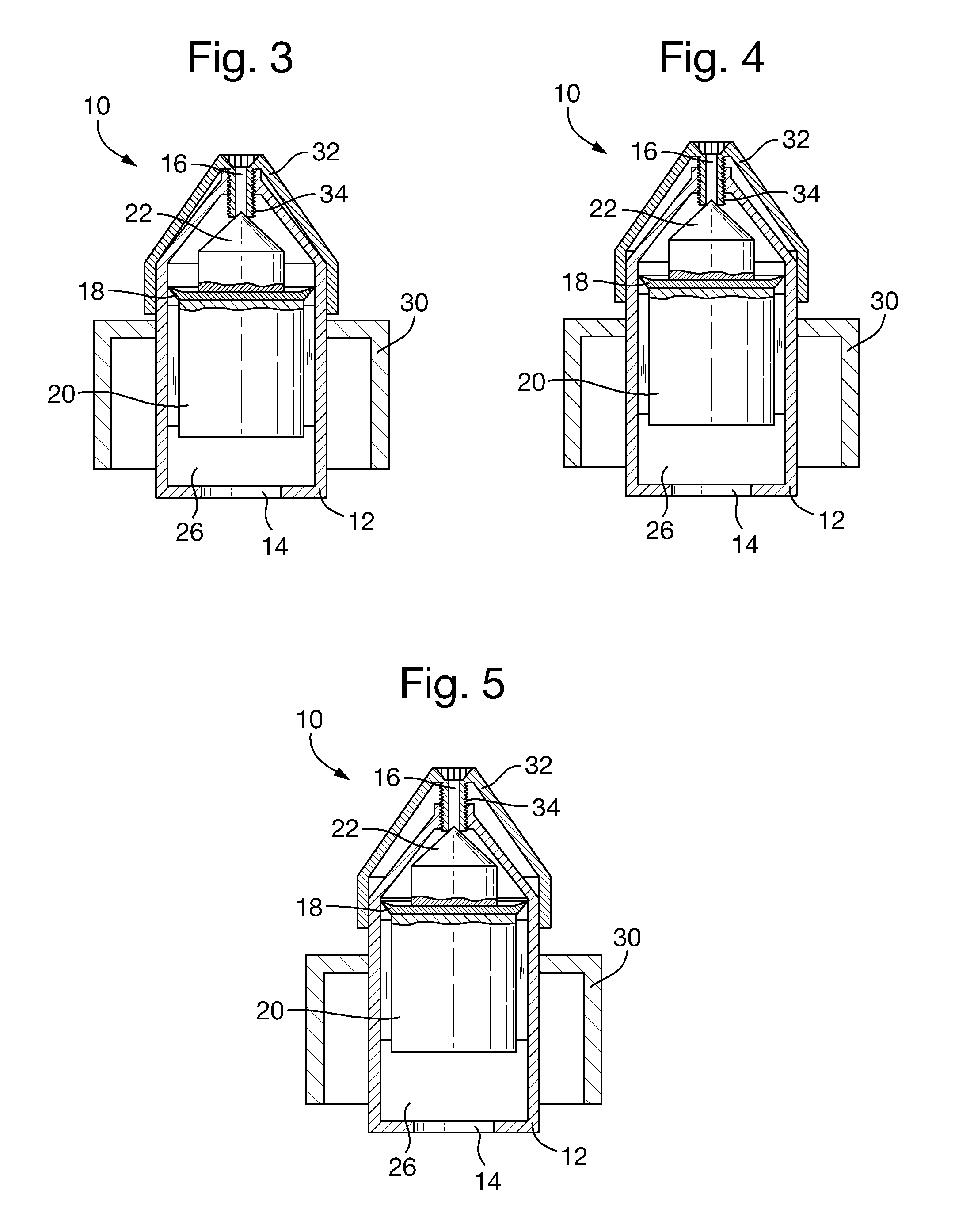
[0009]With such an arrangement, the invention allows the delivery of a fixed amount of liquid from a container, such as a squeezable container, irrespective of how much pressure is applied to the inlet-side liquid volume. Furthermore, fixed amount of liquid can be adjusted by the user so that greater or lesser amounts of liquid can be dispensed, as desired.

[0010]When the dispenser cap is in an unpressurised arrangement and the seal is in its first position (held there by biasing means), an outlet-side liquid volume is present and ready to be dispensed. The user increases the inlet-side liquid pressure, e.g. by squeezing the container. The seal then responds to the increase in pressure and moves towards the outlet, dispensing liquid until it reaches its second position.

[0011]In a preferred embodiment, the seal permits flow of liquid from the inlet-side to the outlet-side provided there is a sufficient pressure difference across it. This is highly counter-intuitive because, on first c...


PUM


Abstract

A dispenser cap (10) for a liquid container having an opening, the cap (10) comprising a means for attachment (30) to the container, a housing (12) inserted into the opening and comprising a liquid inlet (14), a channel and a liquid outlet (16), the channel comprising a moveable seal (18) defining an outlet-side liquid volume (24) and an inlet-side liquid volume (26), the moveable seal (18) is moveable from a first position to a second position towards the liquid outlet (16) by increasing the inlet-side liquid pressure, thereby causing a dispensable volume of liquid flow out of the outlet (16), the moveable seal (18) also comprising a liquid outlet seal means (22) to seal the liquid outlet when the moveable seal (18) is in its second position, thereby preventing further flow of liquid out of the outlet (16), the cap (10) also comprising a dispensable liquid volume adjustment means (32,34) to adjust the fixed volume of dispensable liquid.

Description

TECHNICAL FIELD[0001]The present invention relates to a dispenser cap for a liquid container, or a container comprising the cap integrally formed therewith, which can deliver a fixed dose of liquid reliably and simply.BACKGROUND TO THE INVENTION[0002]Certain liquid compositions are intended to be dispensed and applied in specified quantities. For example cleaning products in liquid form typically instruct the end user to dose particular volumes for a desired cleaning performance to be provided.[0003]One simple solution to this problem is to provide a measuring container with the liquid product. However, this solution, although simple, suffers from the danger of the measuring container becoming lost or separated from the liquid container.[0004]To address this problem, dispensing caps for liquid containers have been developed which are designed to deliver fixed quantities of liquid. As the dispensing cap is integral to the container, it cannot become detached and lost.[0005]However, a...

Claims


Application Information

Patent Timeline
Patent Type & Authority Patents(United States)
IPC IPC(8): B65D37/00B05B11/00B05B11/02B05B11/04G01F11/26G01F11/28
CPCG01F11/263B05B11/3069B05B11/3008B05B11/04G01F11/288B05B11/3067B05B11/3001B05B11/0072B05B11/047B05B11/3076B05B11/0018B05B11/02B05B11/0045B05B11/0059B05B11/00442B05B11/1001B05B11/1008B05B11/1067B05B11/1069B05B11/1076B05B11/027
Inventor VAN, DE, POLL, JONKHEER, THEODOOR, HENDRIK
Owner CONOPCO INC D B A UNILEVER
Why Eureka
Try Eureka