Bicycle derailleur with rotation resistance

a technology of derailleur and bicycle, which is applied in the direction of mechanical equipment, transportation and packaging, and gearing, etc., can solve the problems of unsatisfactory slack in the chain

Active Publication Date: 2014-10-07
SHIMANO INC
View PDF27 Cites 36 Cited by
  • Summary
  • Abstract
  • Description
  • Claims
  • Application Information

AI Technical Summary

Problems solved by technology

However, during rough riding, bumps and shocks may cause the chain guide to rotate counterclockwise, thereby creating undesirable slack in the chain.

Method used


Image

  • Bicycle derailleur with rotation resistance
  • Bicycle derailleur with rotation resistance
  • Bicycle derailleur with rotation resistance

Examples


Embodiment Construction

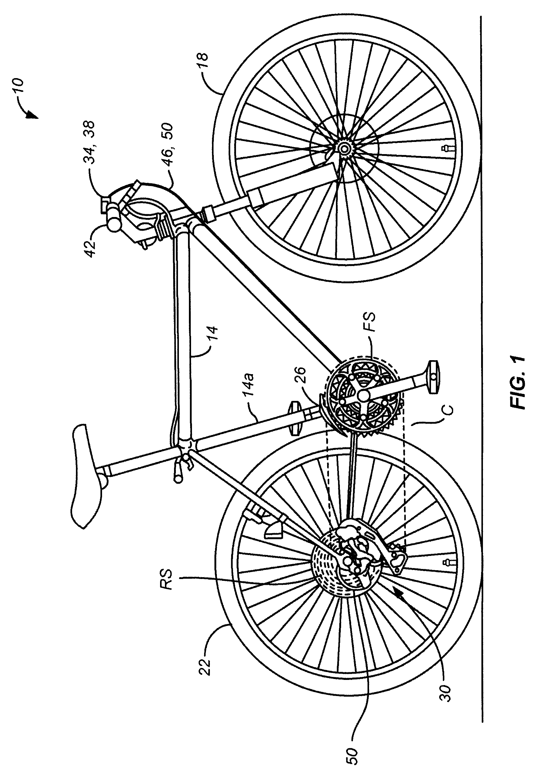
[0044]FIG. 1 shows a bicycle 10 comprising a frame 14 with front and rear wheels 18 and 22 rotatably coupled to frame 14 in a conventional manner. A front derailleur 26 is mounted to a seat tube 14a of frame 14, and a rear derailleur 30 is mounted to the rear of frame 14. Front derailleur 26 switches a chain C among a plurality of front sprockets FS, and rear derailleur 30 switches chain C among a plurality of rear sprockets RS. Conventional shift control devices 34 and 38, mounted to a handlebar 42, are used to control the operation of front derailleur 26 and rear derailleur 30, respectively, through conventional Bowden cables 46 and 50. Bicycle 10 is a conventional bicycle except for rear derailleur 30, so only rear derailleur 30 will be discussed in further detail.

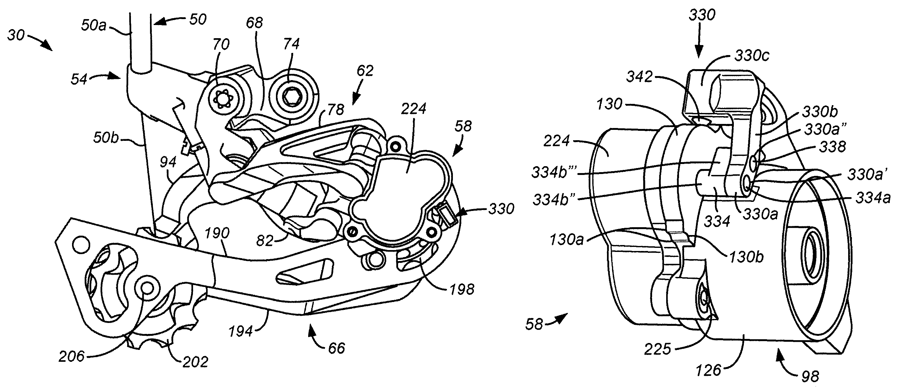
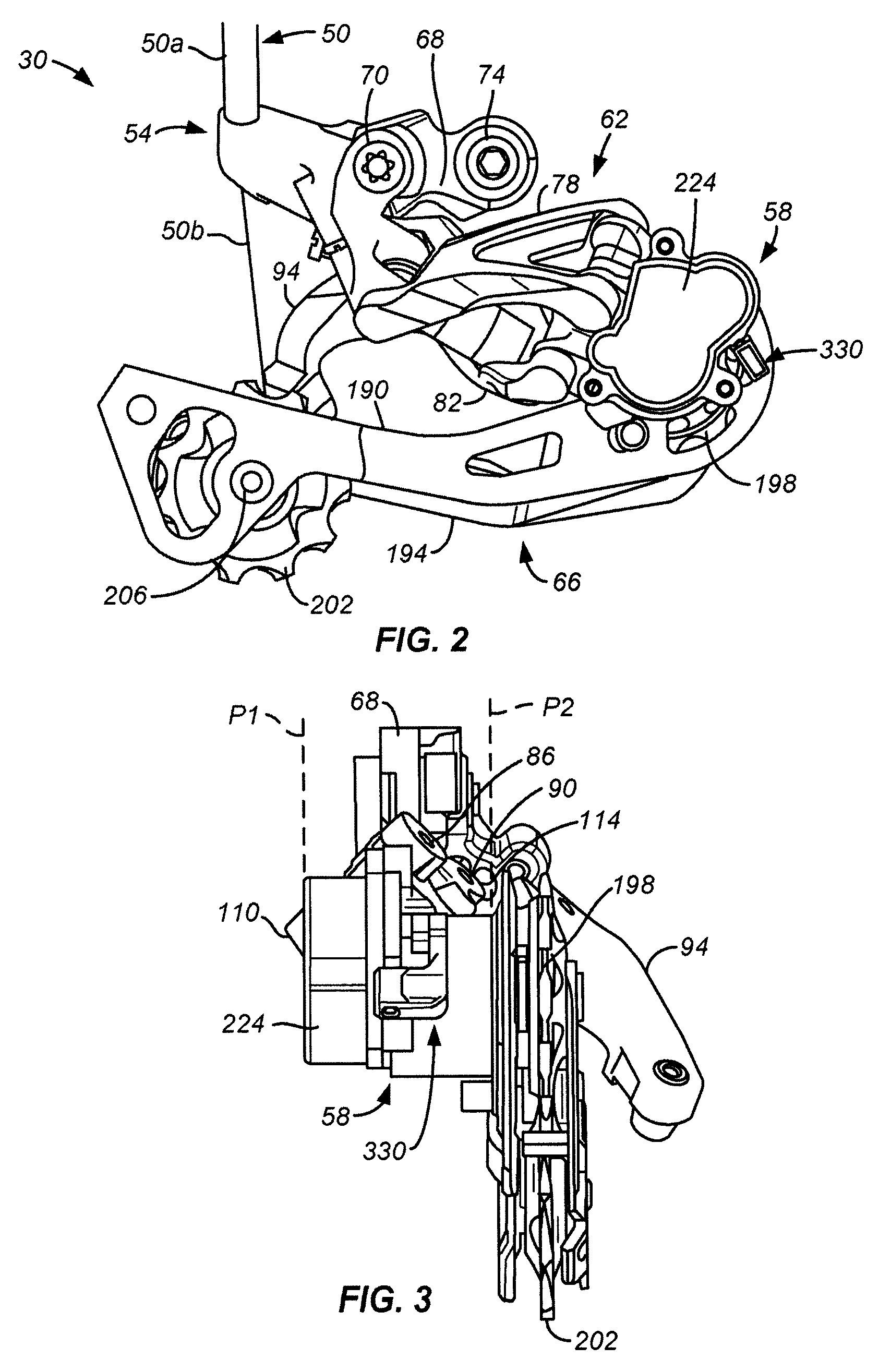
[0045]As shown in FIG. 2, rear derailleur 30 comprises a base member 54, a movable member 58, a linkage assembly 62 and a chain guide 66. Base member 54 is structured to be rotatably mounted to a rear derailleur mountin...


PUM


Abstract

A bicycle derailleur comprises a base member, a movable member movably coupled to the base member, and a chain guide coupled to the movable member for rotation around a rotational axis. A resistance applying element applies resistance to rotational movement of the chain guide, and a resistance control element moves between at least different first and second positions. The resistance control element is operatively coupled to the resistance applying element so that the resistance applying element applies different first and second resistances to rotational movement of the chain guide when the resistance control element is disposed in the respective first and second positions.

Description

CROSS REFERENCE TO RELATED APPLICATIONS[0001]This application is a continuation-in-part of U.S. patent application Ser. No. 12 / 895,705 filed Sep. 30, 2010 and titled “Bicycle Derailleur With Rotation Resistance.”BACKGROUND OF THE INVENTION[0002]The present invention is directed to bicycle transmission devices and, more particularly, to a bicycle derailleur with rotation resistance.[0003]A typical bicycle derailleur transmission includes a plurality of sprockets that rotate together with a front crank or with a rear wheel, a chain, and a derailleur that selectively shifts the chain among the plurality of sprockets. A typical derailleur includes a base member adapted to be mounted to the bicycle frame, a movable member movably coupled to the base member, and a chain guide coupled to the movable member. The chain guide engages the chain to selectively switch the chain among the plurality of sprockets when the movable member moves relative to the base member.[0004]The chain guide of a r...

Claims


Application Information

Patent Timeline
Patent Type & Authority Patents(United States)
IPC IPC(8): B62M9/12B62M9/126
CPCB62M9/126
Inventor YAMAGUCHI, SOTAFUNAI, SHINGOSHAHANA, SATOSHI
Owner SHIMANO INC
Why Eureka
Try Eureka