Piezoelectric speaker

a technology of piezoelectric speaker and speaker body, which is applied in the direction of deaf-aid sets, electrical transducers, transducer details, etc., can solve the problems of sound pressure reduction, and achieve the effect of higher sound pressure and easy realization of desired frequency characteristics

Active Publication Date: 2014-10-14
MURATA MFG CO LTD
View PDF10 Cites 12 Cited by
  • Summary
  • Abstract
  • Description
  • Claims
  • Application Information

AI Technical Summary

Benefits of technology

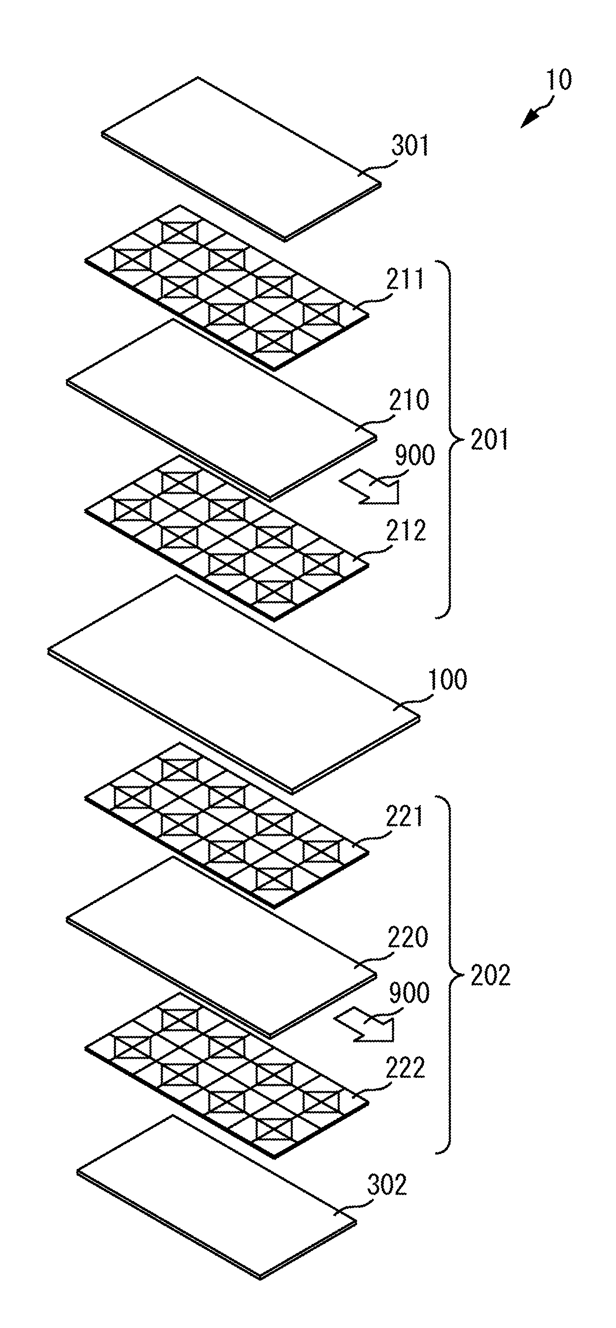
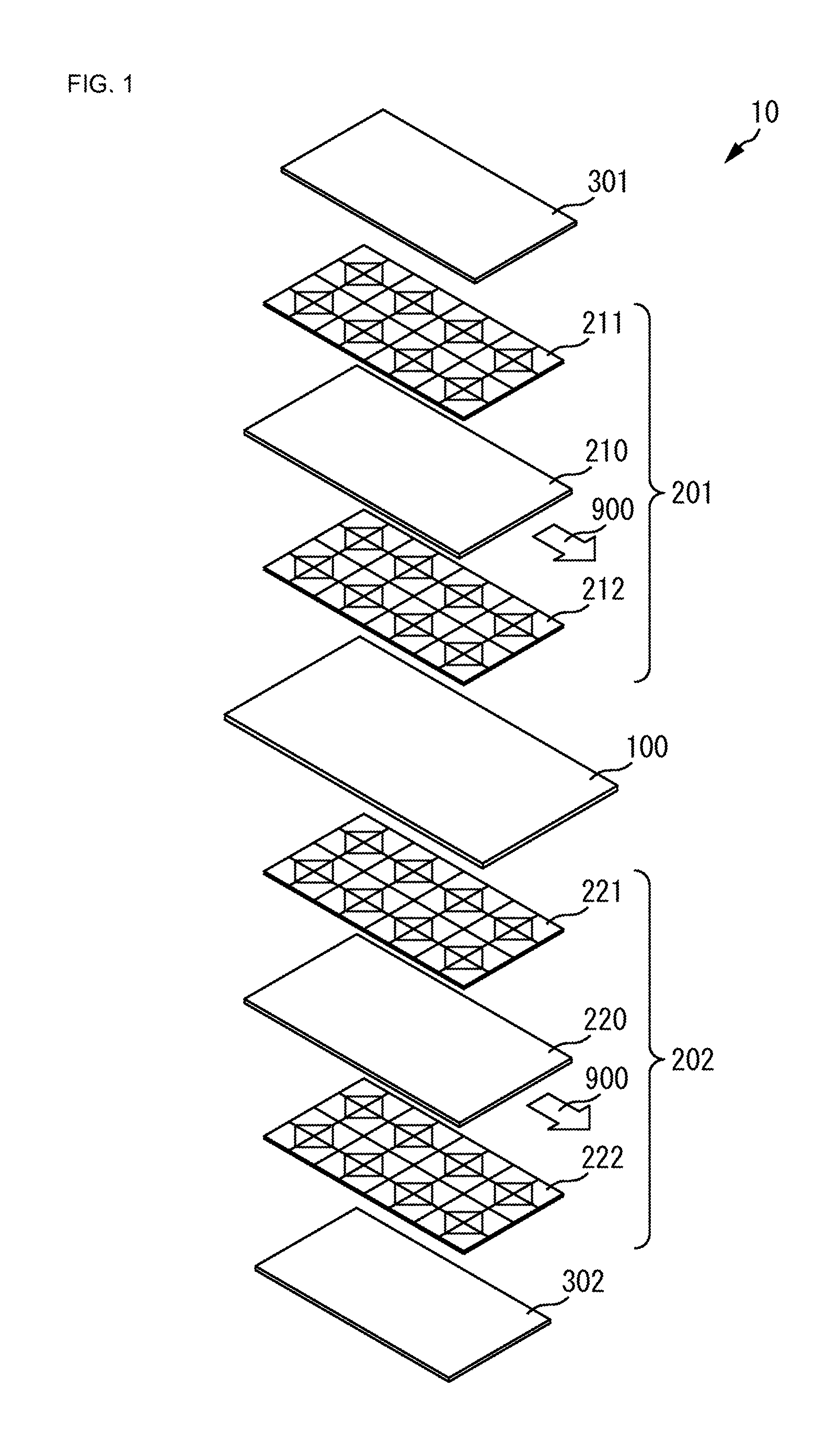
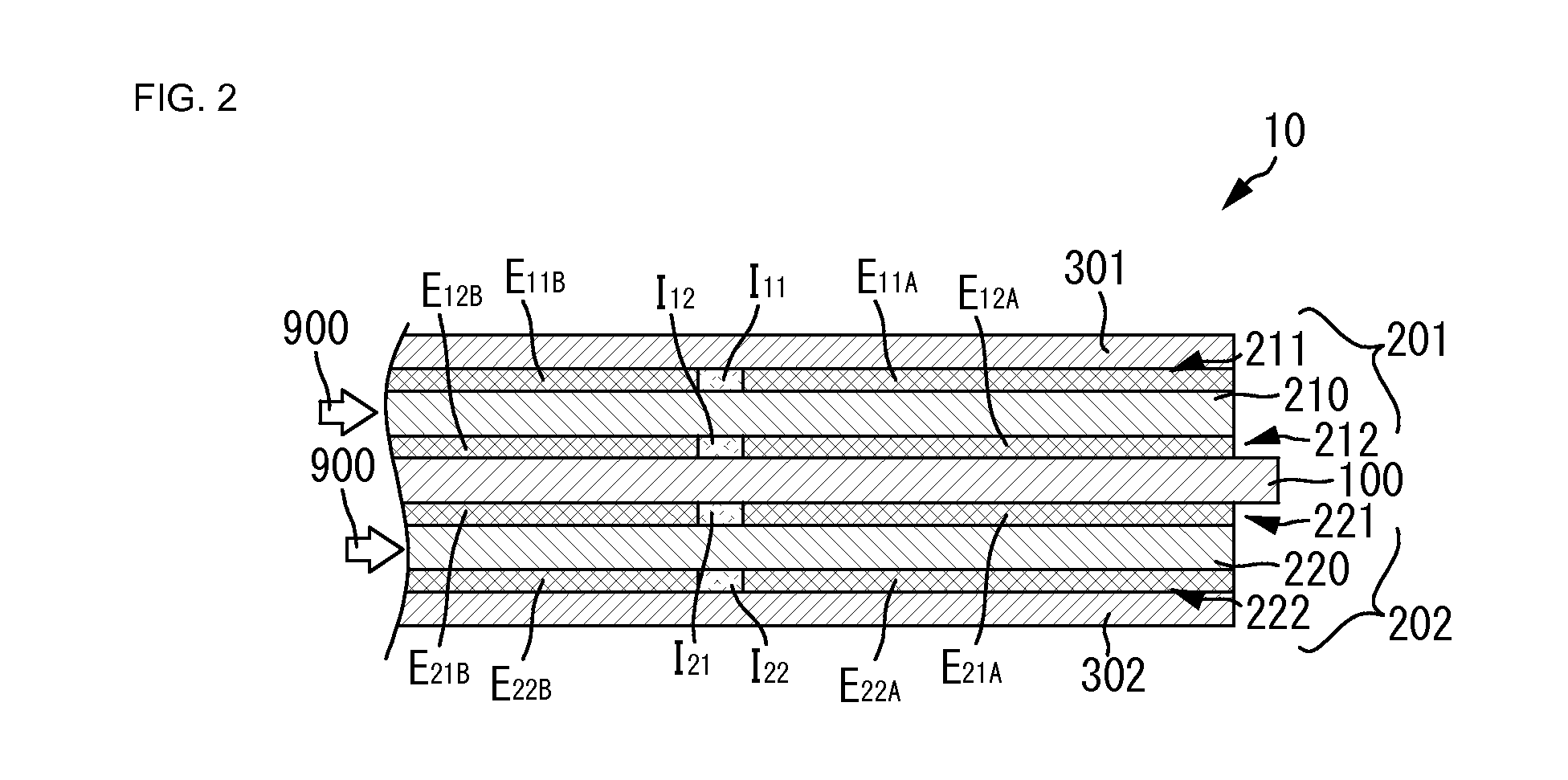
[0008]In this arrangement, plural individual piezoelectric elements that individually vibrate are formed using a single polymer sheet. The substantially synchronized sound emission by the single acoustic driving signal using the plural individual piezoelectric elements allows for the improved sound pressure level compared to the case where a single individual piezoelectric element expanding over the entire polymer sheet as illustrated in FIG. 8C under the condition of the same area and the same driving signal level. Also, frequency characteristics, in particular, frequency characteristics in an audible range above approximately 1000 Hz are improved.
[0031]As such, eight or more individual piezoelectric elements are aligned and formed, so that desired frequency characteristics can be more easily realized.

Problems solved by technology

In the piezoelectric speaker with the piezoelectric polymer sheet as disclosed in Patent Document 1 described above, however, while the sound emitting surface of the piezoelectric polymer sheet is bent to efficiently emit the sound, the plate-shaped sound emitting surface of the piezoelectric polymer sheet is likely to cause the reduction in the sound pressure.

Method used


Image

  • Piezoelectric speaker
  • Piezoelectric speaker
  • Piezoelectric speaker

Examples


first embodiment

[0111]In the first piezoelectric speaker 201B of the present embodiment, further added individual piezoelectric elements are formed at the center of the region in which neighboring 2×2 individual piezoelectric elements are formed for the piezoelectric speaker 201 illustrated in the

[0112]Specifically, an individual piezoelectric element Pe31 is formed which has a new center at the center position of the outer side electrode Eo3 of the individual piezoelectric element Pe11B, the outer side electrode Eo4 of the individual piezoelectric element Pe21B, the outer side electrode Eo1 of the individual piezoelectric element Pe22B, and the outer side electrode Eo2 of the individual piezoelectric element Pe12B.

[0113]In this case, in the outer side electrode Eo3 of the individual piezoelectric element Pe11B, the region opposite to the inner side electrode Ei3 is divided by a dividing line to form the inner side electrode Eic1 of the individual piezoelectric element Pe31B. In the outer side elec...

third embodiment

[0129]Such arrangement allows the number of individual piezoelectric elements to be increased to 23, while the area of the inner side electrode is maintained under the same external shape area of the electrode forming region as the piezoelectric speaker of the

[0130]FIG. 14 is a view illustrating the sound pressure level to frequency characteristics of the piezoelectric speaker according to the present embodiment. The use of the arrangement of the present embodiment allows for the improved flatness of the sound pressure level to frequency characteristics, in particular, in the lower sound range equal to or under 1000 Hz.

[0131]Next, the piezoelectric speaker according to the fifth embodiment will be described by referring to the drawings. FIG. 15A is a plane view depicting, in a simplified manner, an electrode pattern of the piezoelectric speaker according to the fifth embodiment and FIG. 15B is a view for illustrating the electrode pattern of an individual piezoelectric element of th...

ninth embodiment

[0158]The acoustic driving signal is supplied to the piezoelectric speaker apparatus having such arrangement as illustrated in FIG. 23. FIG. 23 is a view illustrating the supplying configuration of the acoustic signal to the piezoelectric speaker apparatus according to the

[0159]The outer side electrode Eo1 of the individual piezoelectric element Pe11, the outer side electrodes Eo1 and Eo3 of the individual piezoelectric element Pe21, the outer side electrode Eo3 of the individual piezoelectric element Pe22, and the outer side electrodes Eo3 of the individual piezoelectric elements Pe23, Pe24, and Pe14 of the piezoelectric speaker 10 are connected to the sound source 11 via a connection wiring pattern 15 and an amplifier 16PR.

[0160]The outer side electrodes Eo2 of the individual piezoelectric elements Pe11, Pe21, Pe22, and Pe23, the outer side electrodes Eo2 and Eo4 of the piezoelectric element Pe24, and the outer side electrode Eo4 of the individual piezoelectric element Pe14 are co...


PUM


Abstract

A piezoelectric speaker that includes a configuration in which a first piezoelectric speaker and a second piezoelectric speaker are respectively arranged adjacent primary surfaces of a plate-shaped base member. The first piezoelectric speaker and the second piezoelectric speaker have the same arrangement, and respective individual piezoelectric elements thereof are arranged so as to correspond to each other when viewed from the direction orthogonal to the primary surfaces of the base member. The first and second piezoelectric speakers include a piezoelectric polymer sheet and electrode patterns of substantially the same shape on both surfaces of the polymer sheet. According to this arrangement, plural individual piezoelectric elements are aligned with each other. A single type of acoustic driving signal is supplied to these plural individual piezoelectric elements in a synchronized manner.

Description

CROSS REFERENCE TO RELATED APPLICATIONS[0001]The present application is a continuation of International application No. PCT / JP2012 / 052810, filed Feb. 8, 2012, which claims priority to Japanese Patent Application No. 2011-025528, filed Feb. 9, 2011, the entire contents of each of which are incorporated herein by reference.FIELD OF THE INVENTION[0002]The present invention relates to a piezoelectric speaker formed with a piezoelectric polymer sheet.BACKGROUND OF THE INVENTION[0003]Conventionally, various types of substantially plate-shaped piezoelectric speakers in which a piezoelectric polymer sheet is used have been proposed. The piezoelectric speakers with a piezoelectric polymer sheet have, for example, a piezoelectric polymer sheet and opposing electrodes formed on both sides of the piezoelectric polymer sheet, such as a flexible speaker disclosed in Patent Document 1. In response that a voltage is applied between the opposing electrodes, an electric field works on the piezoelectr...

Claims


Application Information

Patent Timeline
Patent Type & Authority Patents(United States)
IPC IPC(8): H04R17/00H04R1/22
CPCH04R17/005H04R1/227
Inventor ANDO, MASAMICHIKAWAMURA, HIDEKI
Owner MURATA MFG CO LTD
Why Eureka
Try Eureka