Vehicular power supply device

a power supply device and a technology for vehicles, applied in the direction of engines, machines/engines, instruments, etc., can solve the problems of power generation instability, malfunctions, reset of electrical equipment, etc., and achieve the effect of enhancing engine startability and reducing energy consumption of internal combustion engines

Active Publication Date: 2014-10-14
MITSUBISHI ELECTRIC CORP
View PDF12 Cites 7 Cited by
  • Summary
  • Abstract
  • Description
  • Claims
  • Application Information

AI Technical Summary

Benefits of technology

[0011]The present invention has been made to resolve the foregoing problems and aims at providing a vehicular power supply device in which engine startability can be enhanced by the operation of the starting means at the engine start, whereby the voltage drop at the lead battery attributed to the operation of the starting means can be suppressed, and as a result, energy consumption in the internal combustion engine can be reduced after the automatic start.
[0013]According to the present invention, a vehicular power supply device can be provided that is mounted on a vehicle equipped with an idle stop function, and enhances engine startability by the operation of the starting means as well as suppresses the voltage drop at the lead battery attributed to the operation of the starting means, so as to reduce energy consumption in the engine or other drive sources.

Problems solved by technology

Those vehicles equipped with the idle stop function frequently repeat an automatic stop / start in running in urban areas and the like; therefore, it has now turned out to be technical issues how to reduce racing of the engine revolution speed and noise, secure startability of the engine and suppress a voltage drop at the lead battery at the automatic start.
However, in the configuration shown in Patent Document 1, the lead battery voltage is lowered by discharging of the battery attributed to the operation of the starting means at the automatic start, and as a result, electrical equipment is reset, causing a problem of malfunctions occurring.
Moreover in order to secure the engine startability, the generation voltage is likely to become zero, causing also another problem in that the power generation is unstable after the automatic start.
Moreover in the configuration of Patent Document 2, the engine startability by the operation of the starting means at the automatic start is secured by stopping the generator at the automatic start; however, the lead battery voltage is dropped by the discharging of the battery attributed to the operation of the starting means, causing another problem of malfunctions occurring with the electrical equipment reset.

Method used


Image

  • Vehicular power supply device
  • Vehicular power supply device
  • Vehicular power supply device

Examples


embodiment 1

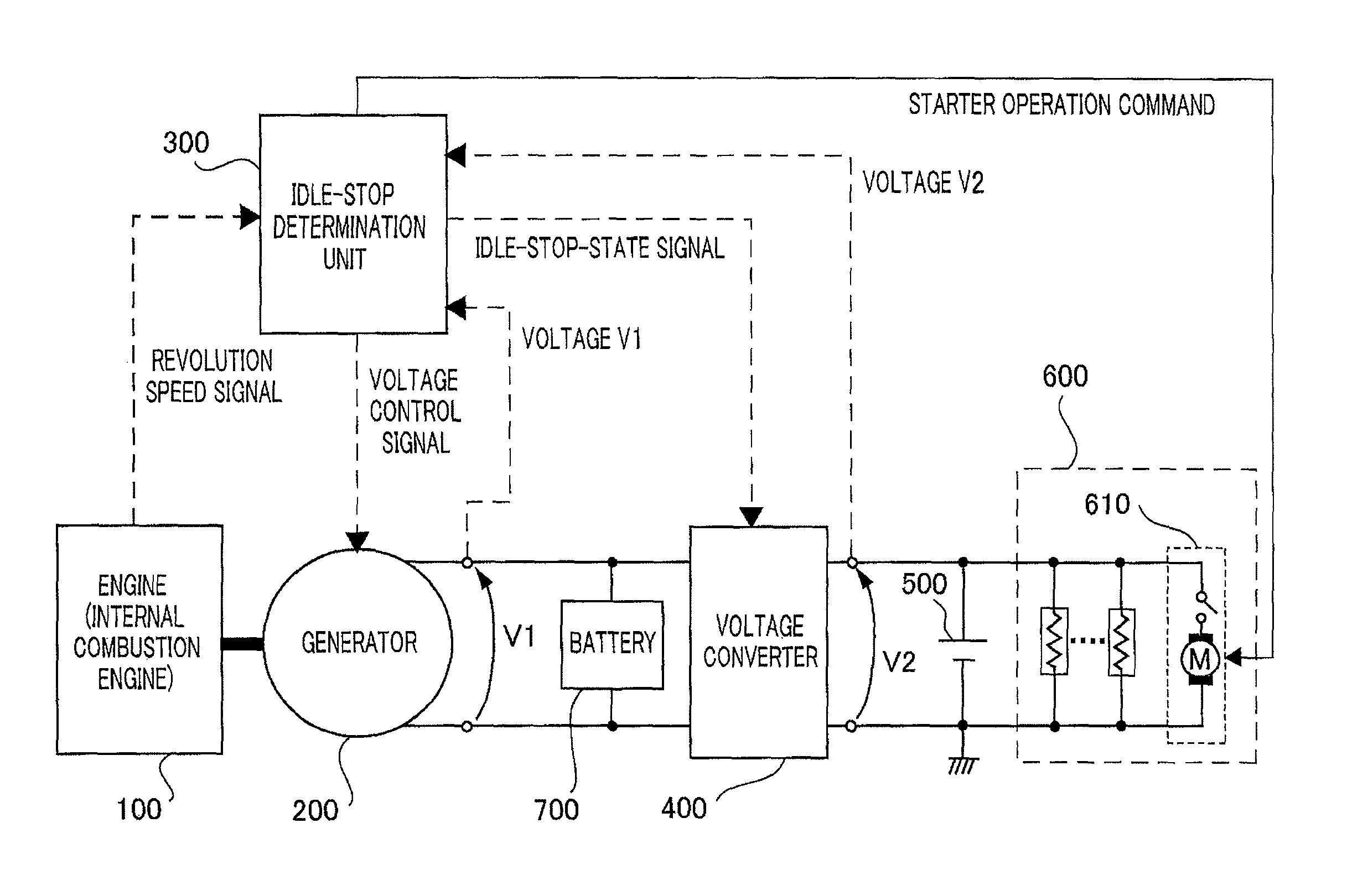
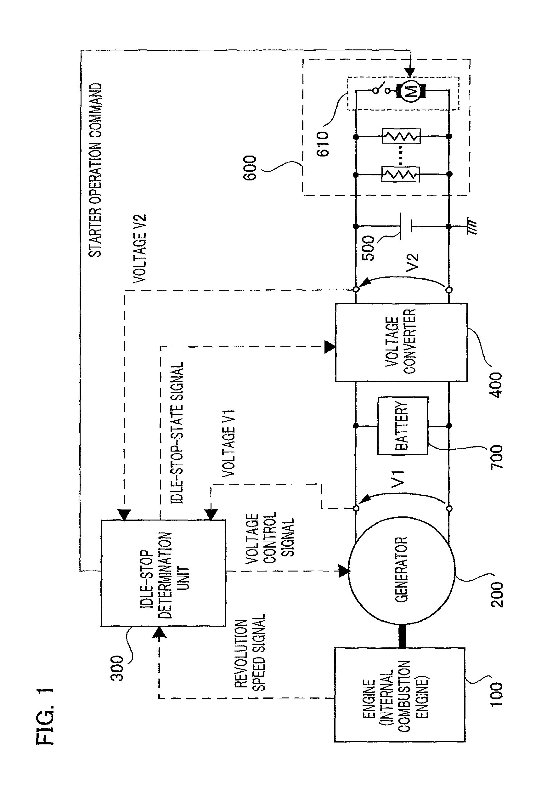
[0024]FIG. 1 shows a configuration diagram for a vehicular power supply device according to Embodiment 1 of the present invention. A generator 200 shown in FIG. 1 is, for example, an alternator or MG (Motor-Generator) including a rectifier, which is mechanically connected by a belt to a revolving portion of an engine 100 (internal combustion engine, not shown in the figure). An idle-stop determination unit 300 is an ECU, for example, which computes a target DC voltage generated by the generator 200 and controls a voltage generated by the generator 200 to become the target DC voltage. A battery 700 is an electric double layer capacitor, for example, which is charged with a DC voltage of V1 output from the generator 200, and supplies an onboard electrical load 600 with a current by way of an voltage converter 400. The voltage converter 400 converts the DC voltage V1 output from the generator 200 into a first DC voltage control value V2 and outputs the resultant value. The reference nu...

embodiment 2

[0058]FIG. 6A and FIG. 6B each show a control flow for a voltage converter 400 according to Embodiment 2 of the present invention. Step S9 in Embodiment 1 is replaced with Step S9b here.

[0059]In Step S9b, the idle-stop determination unit 300 determines, from the revolution speed of the engine started by the operation of the starter 610 at an automatic start request, whether to control the DC voltage control value at the output side of the voltage converter 400 to become the second DC voltage control value V2a or to become the first DC voltage control value V2. If the engine revolution speed reaches a predetermined value (idle revolution speed, for example) after discharging attributed to the operation of the starter 610 after cranking, Step S10 ensues. Meanwhile, if the engine revolution speed does not reach the predetermined value, Step S9b continues and the voltage converter 400 continues controlling of the DC voltage control value at the output side thereof to become the second D...

embodiment 3

[0070]FIG. 8 is a configuration diagram for a vehicular power supply device according to Embodiment 3 of the present invention. This configuration differs from the configuration shown in FIG. 1 in that information on a current supplied to the electrical load from the voltage converter 400 is output to the idle-stop determination unit and the idle-stop determination unit outputs to the voltage converter 400 a third DC voltage control value V2b.

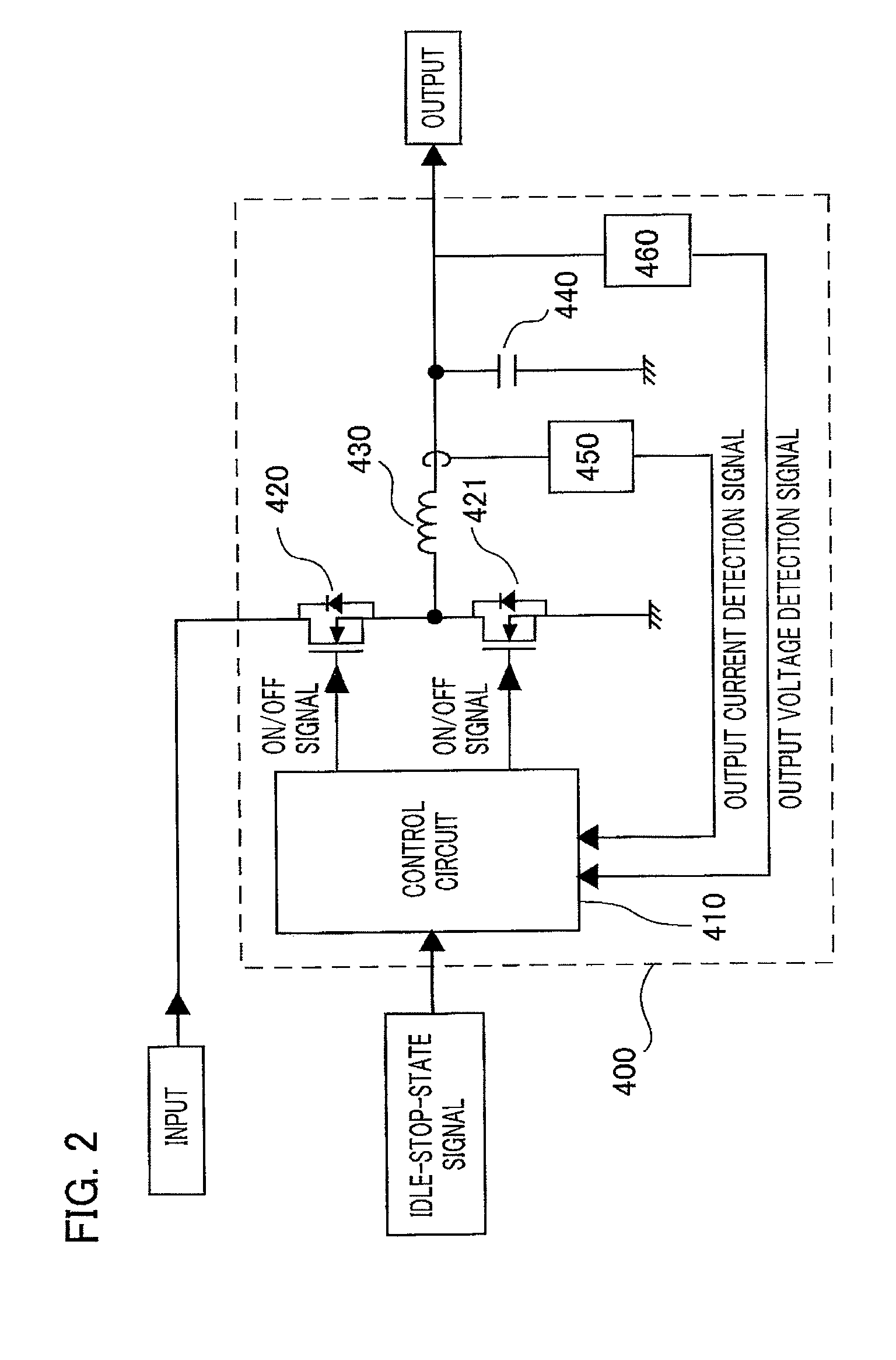
[0071]FIG. 9 shows the configuration of a voltage converter 400 according to Embodiment 3 of the invention. The voltage converter 400 has the same configuration as that in FIG. 2; however they differ from each other in that the information on the current supplied to the electrical load, detected by the current detection means 450 is output to the idle-stop determination unit 300 from the control circuit 410 included in the voltage converter 400 and the idle-stop determination unit 300 inputs the third DC voltage control value V2b to the contro...


PUM


Abstract

A vehicular power supply device mounted on a vehicle equipped with an idle stop function is provided that enhances engine startability and suppresses a voltage drop at a battery driving the starter, so as to reduce energy consumption by the engine or other drive sources. The device includes a voltage converter for converting a DC voltage V1 output from a generator into a DC voltage control value V2 and for outputting the value, and when the idle-stop determination unit determines that the engine is in the idle stop state, the voltage converter outputs, depending on a current and voltage supplied to an electrical load including a starter, a second DC voltage control value V2a higher than a first DC voltage control value V2 that is a target output voltage for the battery.

Description

BACKGROUND OF THE INVENTION[0001]1. Field of the Invention[0002]The present invention relates to a vehicular power supply device mounted on a vehicle equipped with an idle stop function of automatically stopping / starting the engine (internal combustion engine) serving as a drive source of the vehicle.[0003]2. Description of the Related Art[0004]In order to decrease burdens on the environment, vehicles equipped with an idle stop function (automatic stop / start system) have been increasing in number in recent years, aiming at enhancing gas mileage. Those vehicles equipped with the idle stop function frequently repeat an automatic stop / start in running in urban areas and the like; therefore, it has now turned out to be technical issues how to reduce racing of the engine revolution speed and noise, secure startability of the engine and suppress a voltage drop at the lead battery at the automatic start.[0005]In Patent Document 1, in a vehicle equipped with the idle stop function and with ...

Claims


Application Information

Patent Timeline
Patent Type & Authority Patents(United States)
IPC IPC(8): F02D28/00B60R16/03F02N11/08
CPCB60R16/03F02N11/0866F02N2011/0888F02N11/0814
Inventor UBUKATA, TAKAYUKIITOI, NAOKIKIHARA, NOBUHIRO
Owner MITSUBISHI ELECTRIC CORP
Why Eureka
Try Eureka