Variable valve actuating apparatus and process for internal combustion engine

a technology of variable valve and operating apparatus, which is applied in the direction of valve arrangement, combustion engine, machine/engine, etc., can solve the problems of inability to reliably lock the vane, inability to reduce the emission sufficiently, and unstable idling operation of the engine, so as to improve the startability of the engin

Inactive Publication Date: 2010-09-28
HITACHI LTD
View PDF12 Cites 4 Cited by
  • Summary
  • Abstract
  • Description
  • Claims
  • Application Information

AI Technical Summary

Benefits of technology

[0008]It is, therefore, a main object of the present invention to provide variable valve actuating apparatus and / or process to improve the startability or starting performance of an engine more reliably.
[0010]According to still another aspect of the present invention, a variable valve actuating apparatus for an internal combustion engine, comprises: a first valve actuating mechanism to vary a first valve operating condition of the engine; a second valve actuating mechanism to vary a second valve operating condition of of the engine; and a controller to detect an actuating position of the second valve actuating mechanism, to determine a desired target position of the first valve actuating mechanism in accordance with the actuating position of the second valve actuating mechanism so as to improve a startability of the engine, to control the first valve actuating mechanism to the target position, and to crank the engine after an operation to control the first valve actuating mechanism to the target position.
[0011]According to still another aspect of the present invention, a control process of controlling a variable valve actuating apparatus including a first valve actuating mechanism to vary a first valve operating condition of an internal combustion engine, and a second valve actuating mechanism to vary a second valve operating condition of of the engine, the control process comprises: a first process element of detecting an actuating position of the second valve actuating mechanism; a second process element of determining a desired target position of the first valve actuating mechanism in accordance with the actuating position of the second valve actuating mechanism so as to improve a startability of the engine; a third process element of controlling the first valve actuating mechanism to the target position; and a fourth process element of allowing a cranking operation of the engine after an operation to control the first valve actuating mechanism to the target position.

Problems solved by technology

However, in the variable valve actuating system of the above-mentioned patent document, it is difficult to lock the vane reliably by aligning the lock pin with a lock hole in various engine stopping situations such as hard braking and engine stall.
Accordingly, this system may allow unstable behavior of the vane after a stop of the engine, and may be unable to reduce the emission sufficiently in a cold start of the engine.
Moreover, if the engine is not cold but warm at the time of a next engine restart, even if the lock pin is engaged in the lock hole, an idling operation of the engine may be unstable because of a large valve overlap despite engagement between the lock pin and the lock hole.

Method used


Image

  • Variable valve actuating apparatus and process for internal combustion engine
  • Variable valve actuating apparatus and process for internal combustion engine
  • Variable valve actuating apparatus and process for internal combustion engine

Examples


first embodiment

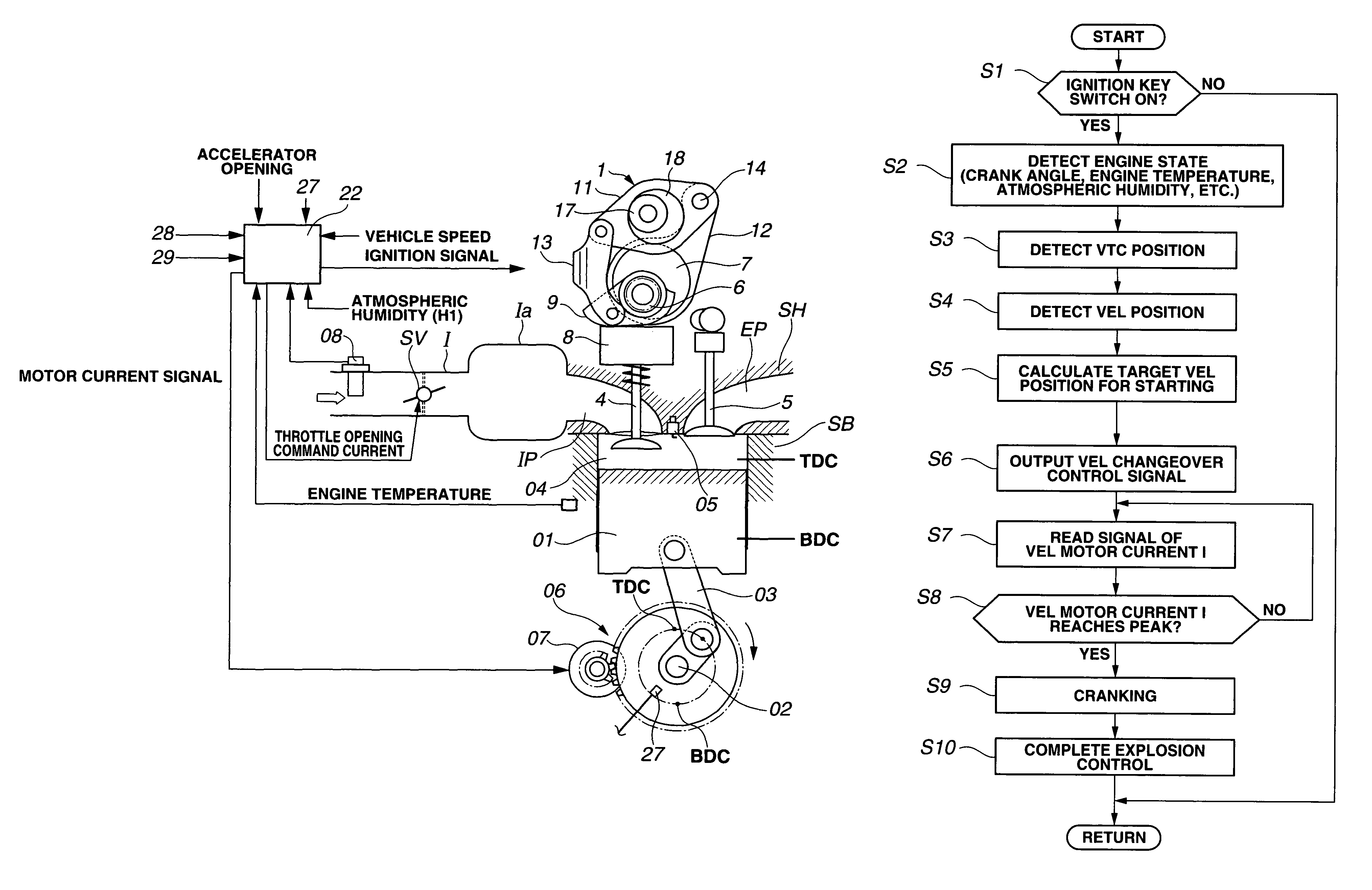
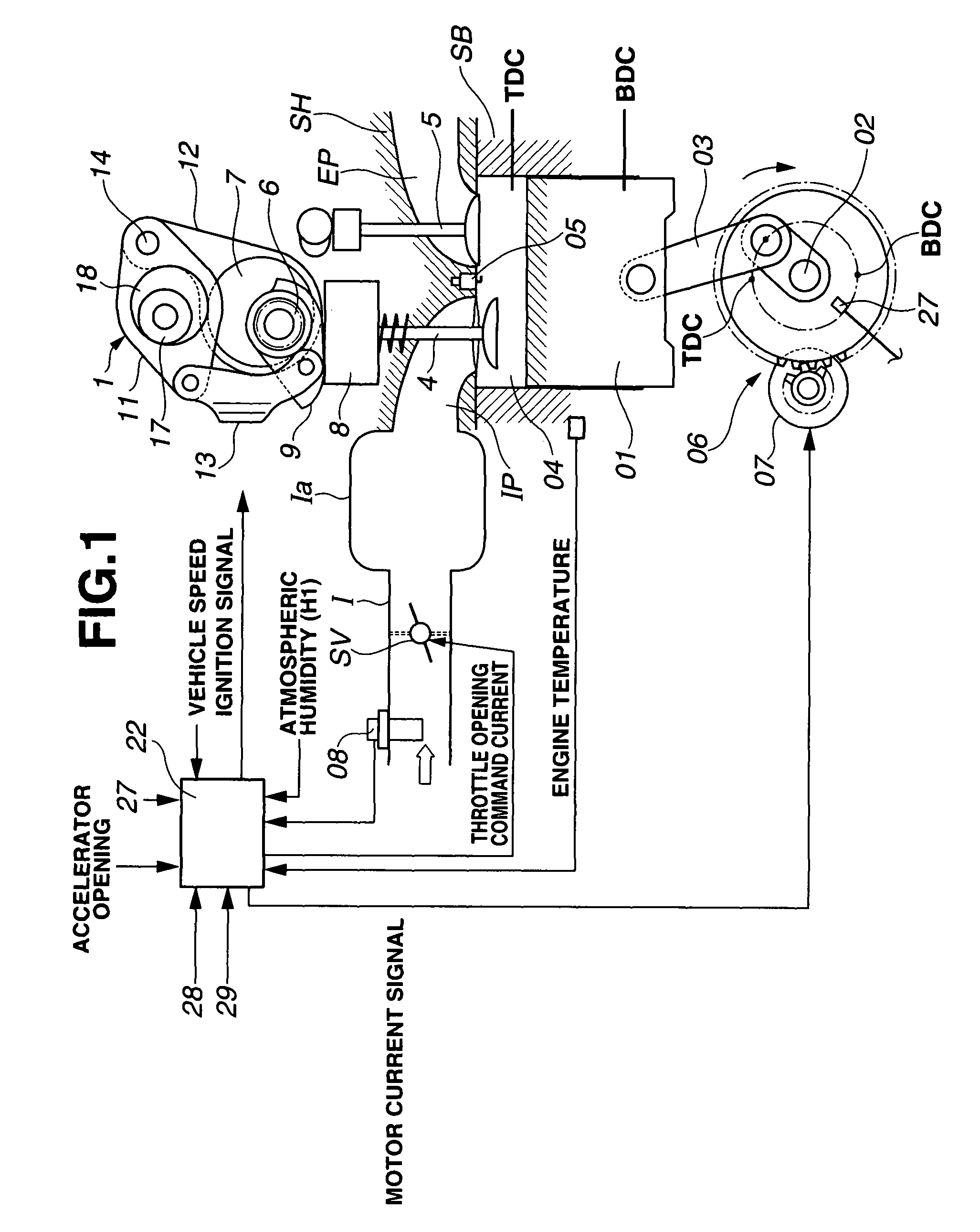
[0031]FIG. 1 schematically shows an engine system including a variable valve actuating system or apparatus according to the present invention. In this embodiment, the internal combustion engine is a four-cycle multi-cylinder internal combustion engine, and the variable valve actuating system is applied to the intake valve's side.

[0032]A cylinder bore shown in FIG. 1 is formed in a cylinder block SB of the engine. A piston 01 is received in this cylinder bore so that piston 01 can slide up and down in the cylinder bore. Intake and exhaust ports IP and EP are formed in a cylinder head SH. For each cylinder, there are provided a pair of intake valves 4, and a pair of exhaust valves 5 for opening and closing the respective open ends of the intake and exhaust ports. Piston 01 is connected with a crankshaft 02 through a connecting rod 03. A combustion chamber 04 is formed between the crown of piston 01 and a lower surface of cylinder head SH.

[0033]In an intake passage I on the upstream si...

second embodiment

[0106]FIG. 12 shows a control process performed by controller 22 according to the present invention, which is adequate especially when starting vibrations is liable to occur as in warm-up starting. Steps S11˜S14 are substantially identical to steps S1˜S4. That is, controller 22 examines whether the ignition key switch is on at S11; detects the current engine state at S12 when the ignition key switch is on; and detects the current positions of valve timing control mechanism 2 and valve lift varying mechanism 1 at S13 and S14.

[0107]At a step S15, controller 22 checks the position of the piston in at least one cylinder on the intake stroke or the compression stroke by using the current crank angle read from crank angle sensor 27, and examines whether the piston position on the intake stroke or the compression stroke is away from the bottom dead center by a separation (or distance) greater than or equal to a predetermined value. When the separation of the piston position from the bottom...

third embodiment

[0122]In the third embodiment, therefore, it is possible to employ, as the position sensor of valve timing control mechanism 2, a trigger sensor capable of sensing at time intervals during rotation, instead of a costly absolute angle sensor, and thereby to reduce the production cost.


PUM


Abstract

A variable valve actuating apparatus for an internal combustion engine includes a first valve actuating mechanism to vary a first valve operating condition, and a second valve actuating mechanism to vary a second valve operating condition. A controller controls the first valve actuating mechanism to satisfy a predetermined engine starting condition before a start of a cranking operation or during the cranking operation, with respect to an engine operating condition including the second valve operating condition controlled by the second valve actuating mechanism.

Description

BACKGROUND OF THE INVENTION[0001]The present invention relates to variable valve operating apparatus suitable for improving engine starting performance.[0002]There is a demand for accurate control of a valve timing (opening timing and / or closing timing) of an engine valve, especially of an intake valve at an initial stage of an engine starting operation, for recent stringent regulations against exhaust emission, and increase of frequency of engine restarts in a hybrid vehicle.[0003]To this end, there are proposed various valve actuating apparatus for controlling the opening and closing timings of an engine valve in accordance with an engine operating condition by varying a relative rotational phase between a timing sprocket and a vane fixed to a camshaft by the use of oil pressure.[0004]In the case of such a hydraulic actuating mechanism, when the engine speed is very low as in an engine starting operation, a control oil pressure is low and the hydraulic power for changeover is insu...

Claims


Application Information

Patent Timeline
Patent Type & Authority Patents(United States)
IPC IPC(8): F01L1/34
CPCF01L1/022F01L1/3442F01L13/0026F02D13/023F01L2001/0537F01L2001/34426F01L2001/34469F01L2001/34483F01L2013/0073F01L2800/01F02D13/0238F02D13/0269F02D2013/0292Y02T10/142Y02T10/18Y02T10/12
Inventor NAKAMURA, MAKOTOHARA, SEINOSUKE
Owner HITACHI LTD
Why Eureka
Try Eureka