Pool skimmer basket system

a technology for skimmers and accessories, applied in swimming pools, filtration separation, separation processes, etc., can solve the problems of constant maintenance of skimmers, particularly unappealing, and skimmer baskets b>160/b>, and achieve the effect of increasing the speed of water flowing and increasing the speed of water

Active Publication Date: 2014-10-21
TOTALLY NEW TECH
View PDF16 Cites 14 Cited by
  • Summary
  • Abstract
  • Description
  • Claims
  • Application Information

AI Technical Summary

Benefits of technology

[0017]Preferably the system is used in a method of increasing the velocity of water flowing into a skimmer basket that includes a) providing the system and b) flowing water and debris through the slot of the second tube, through the slot of the first tube, into the first tube interior, and into the skimmer basket interior. Optionally, the method further includes rotating the second tube relative to the first tube. Optionally, the method further includes the step of rotating the second tube relative to the first tube so that the second tube partially covers the first tube slot, and rotation of the second tube relative to the first tube so that the second tube partially covers the first tube slot increases the velocity of water and debris entering the basket.

Problems solved by technology

Unfortunately, swimming pool skimmers 100 have a number of problems.
Thus, skimmer baskets 160 are a constant maintenance issue.
This is particularly unappealing since creatures like snails and spiders are attracted to skimmers 110.
Third, many swimming pool pumps 190 lack sufficient suction force due to safety requirements such as the Virginia Graeme Baker Pool and Spa Safety Act in the United States.
Consequently, too often debris water is sucked into the skimmer 100 at too low of a rate, leaving the pool 110 dirty.
This is especially problematic in the case of cheap plastic baskets 160 with weak handles 166.
Although the diverter plate of the '416 patent claims to increase suction power, it does nothing to address the lack of capacity of the skimmer basket 160, the fact that a pool owner has to dip his or her hands into dirty water to remove the skimmer basket 160, or breakage of basket handles 166.
The '350 patent also does not address the flow rate of water into the basket 160.
The '279 patent does not teach or suggest a system that has an inner and outer tube that are attached to a skimmer basket.

Method used


Image

  • Pool skimmer basket system
  • Pool skimmer basket system
  • Pool skimmer basket system

Examples


Embodiment Construction

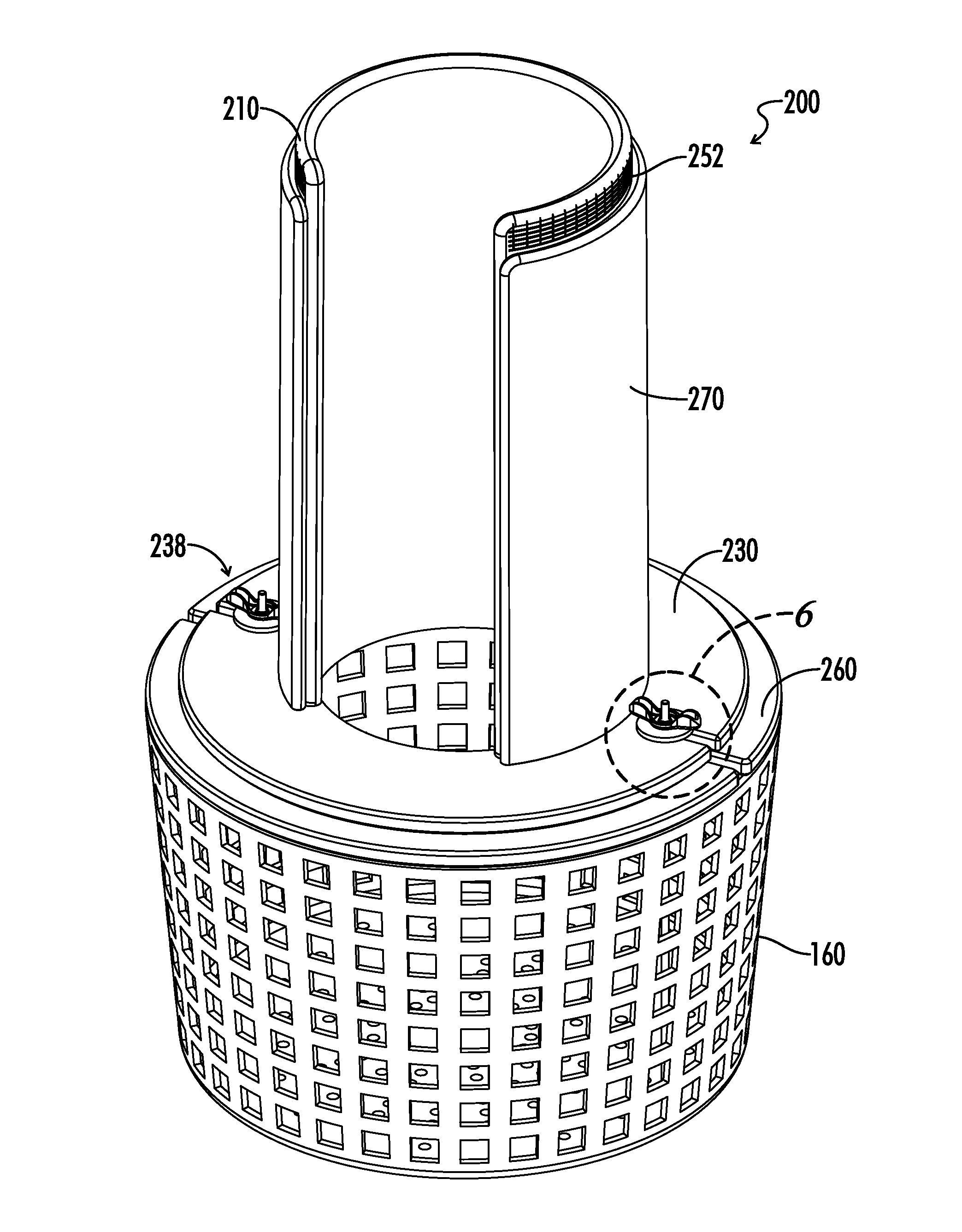
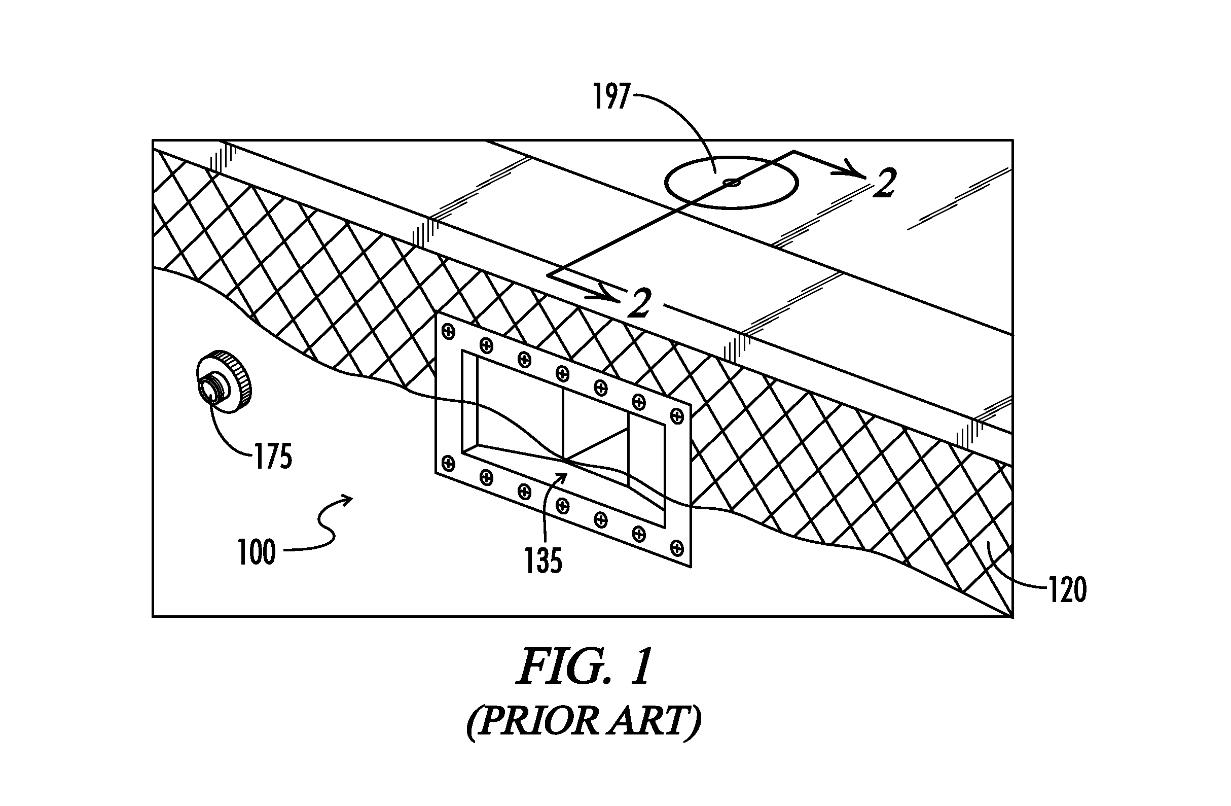
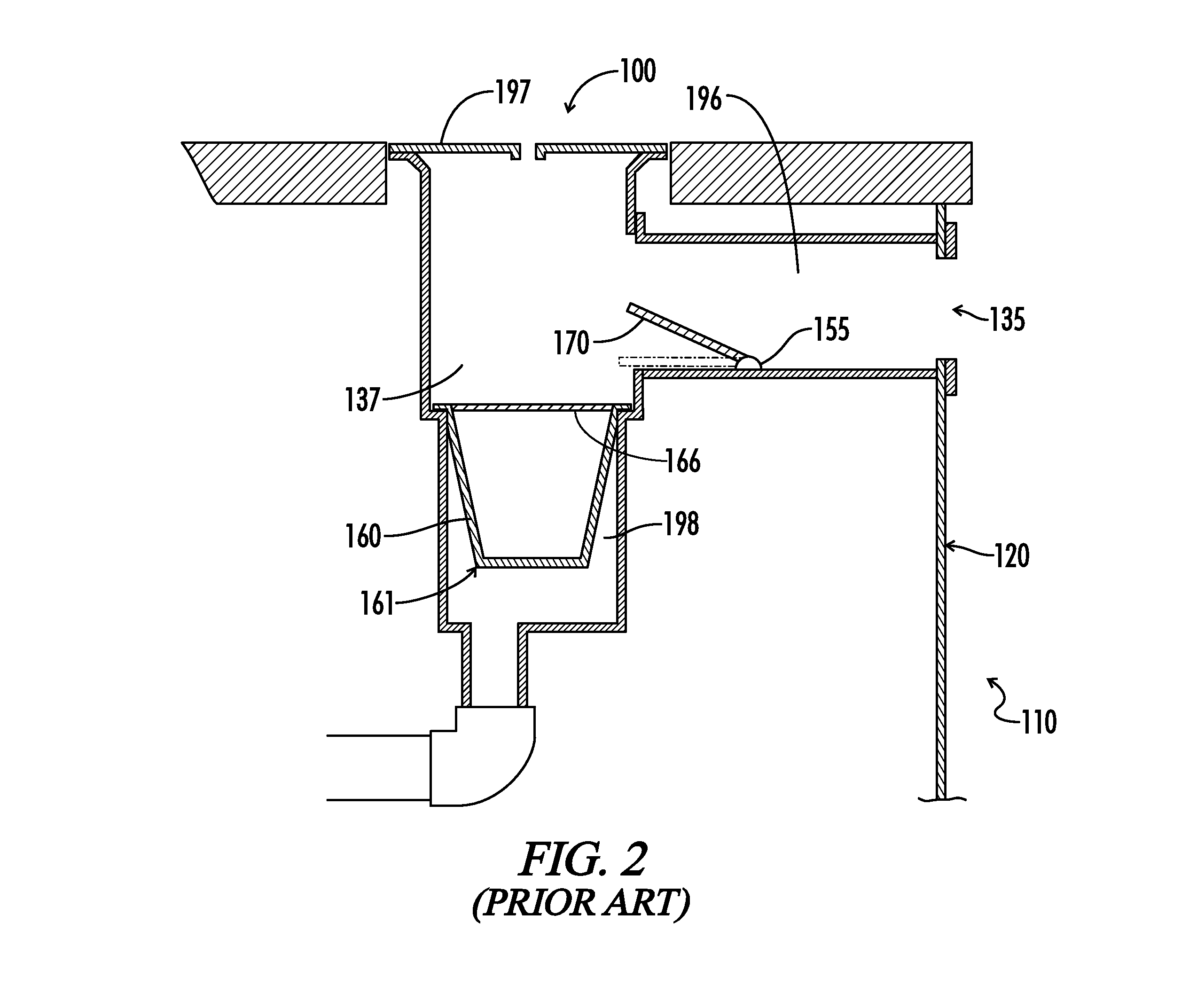
[0056]The present disclosure provides a system 200 for improving a pool skimmer 100. In the drawings, not all reference numbers are included in each drawing for the sake of clarity. It will be understood that references herein to the singular form of a term encompass plural forms. The system 200 may be used in conjunction with any suitable pool skimmer, and are preferably used with immobile skimmers that are located in swimming pool, pond, fountain, or spa sidewalls, such as the skimmer 100 illustrated in FIGS. 1-3. As used herein, the term “pool” means a swimming pool, pond, fountain or spa. While, the system 200 may be used in spas, it will be appreciated that the system 200 is preferably used in swimming pools, given that spas generally have a small surface area and collect less debris than pools.

[0057]Referring further to the system 200, as shown in FIGS. 4-36 the system 200 includes a skimmer basket 160 configured to be placed in the interior 137 of a pool skimmer 100. The skim...


PUM

PropertyMeasurementUnit
widthaaaaaaaaaa
widthaaaaaaaaaa
diameteraaaaaaaaaa

Abstract

The present invention relates to apparatuses for improving pool skimmers. In some embodiments, the apparatus is a pool skimmer basket system that includes a skimmer basket, a first tube that is attached to the skimmer basket, and a second tube that is adjacent to and rotatable relative to the first tube. The first tube includes a longitudinal slot that feeds water into the skimmer basket. Without being bound by any particular theory, it is believed that the slot increases the velocity of water flowing into the basket and that the system increases the debris-holding capacity and allows one to avoid having to reach through dirty water to remove the skimmer basket.

Description

RELATED APPLICATIONS[0001]This application is a continuation of International Patent Application PCT / US14 / 31757, filed Mar. 25, 2014, which is a continuation-in-part of U.S. patent application Ser. No. 14 / 023,415, filed Sep. 10, 2013.BACKGROUND[0002]1. Technical Field[0003]The present invention relates to apparatuses for improving the operation of pool skimmers, particularly those used in swimming pools, and methods of using the same.[0004]2. Background of the Invention[0005]With reference to FIGS. 1-3, in the prior art, it is known to remove debris in swimming pools 110 through the use of skimmers 100. Skimmers 100 generally include a rectangular skimmer opening 135 located in a sidewall 120 of the swimming pool 110, a moveable weir 170 that pivots on a hinge 155 within the skimmer 100 and moves in response to changes in the water levels of the swimming pool 110, and a skimmer basket 160. The skimmer basket 160 sits in a well 198 located in the interior 137 of the skimmer 100, coll...

Claims


Application Information

Patent Timeline
Patent Type & Authority Patents(United States)
IPC IPC(8): E04H4/12
CPCE04H4/16E04H4/1272E04H4/1209
Inventor SMITH, RONNIE, E.
Owner TOTALLY NEW TECH
Why Eureka
Try Eureka