Multi-touch tracking

a multi-touch and tracking technology, applied in the direction of instruments, electric digital data processing, input/output processes of data processing, etc., can solve the problems of computationally difficult to track the touch, beyond the capabilities of a microcontroller, etc., to achieve sufficient simple operation, less computation time, and few simple calculations

Active Publication Date: 2014-10-21
NEODRON LTD
View PDF34 Cites 0 Cited by
  • Summary
  • Abstract
  • Description
  • Claims
  • Application Information

AI Technical Summary

Benefits of technology

[0020]Significantly, the method avoids the need to calculate the separation distances of all of the possible paths between the multiple touch locations, and instead uses a selective recalculation only when needed to prevent a single touch in one time frame being paired with multiple touches in another time frame. The method also avoids complex algebra and floating point operations, and has little memory requirement, since all processing is based on comparing only two touch data sets and does not involve any path prediction or historical velocity considerations taken from multiple preceding time frames.
[0023]The advantage of the claimed invention is that objects adjacent a touch panel can be tracked between polling cycles or time-frames using a few simple calculations and less computation time.
[0024]The invention therefore provides a reliable multitouch tracking algorithm that is sufficiently simple to run in real time on a microcontroller, or other integrated circuit device with limited processing power and memory capacity. The multitouch tracking algorithm is preferably hosted in non-volatile memory on the microcontroller. During operation, the microcontroller will output data to an output port in the form of touch co-ordinates ordered in, or tagged by, tracked touches obtained by the method of the invention.

Problems solved by technology

Therefore, it becomes computationally difficult to track the touches as the number of touches increase, especially if a microcontroller is to be used.
This method uses full scale numeric processing requiring a digital signal processor or microprocessor, and is beyond the capabilities of a microcontroller.

Method used


Image

  • Multi-touch tracking
  • Multi-touch tracking
  • Multi-touch tracking

Examples


Embodiment Construction

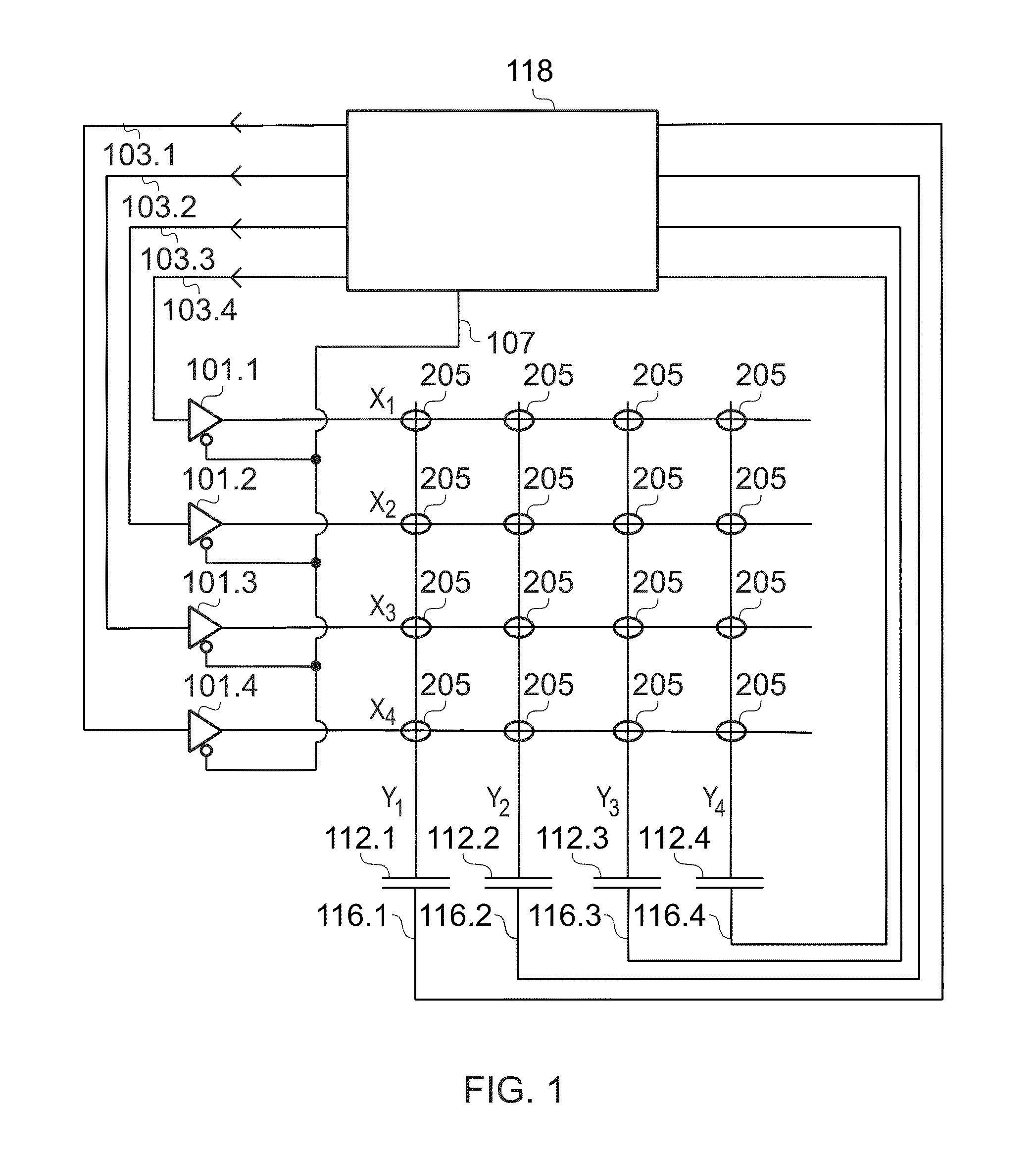
[0033]FIG. 1 is a circuit diagram illustrating a touch sensitive matrix providing a two-dimensional capacitive transducing sensor arrangement according to an embodiment of the invention. The touch panel shown in FIG. 1 has 4 row electrodes and 4 column electrodes. It will be appreciated that the number of columns and rows may be chosen as desired, another example being twelve columns and eight rows or any other practical number of columns and rows.

[0034]The array of sensing nodes is accommodated in or under a substrate, such as a glass panel, by extending suitably shaped and dimensioned electrodes. The sensing electrodes define a sensing area within which the position of an object (e.g. a finger or stylus) to the sensor may be determined. For applications in which the sensor overlies a display, such as a liquid crystal display (LCD), the substrate may be of a transparent plastic material and the electrodes are formed from a transparent film of Indium Tin Oxide (ITO) deposited on the...


PUM


Abstract

A method of tracking multiple touches over time on a touch sensor, for example a capacitive touch screen. The method analyzes first and second touch data sets from adjacent first and second time frames. First, the touch data sets are analyzed to determine the closest touch in the second time frame to each of the touches in the first time frame, and calculating the separation between each such pair of touches. Then, starting with the pair of touches having the smallest separation, each pair is validated until a pairing is attempted between touches for which the touch in the second time frame has already been paired. At this point, the as-yet unpaired touches from the first and second touch data sets are re-processed by re-applying the computations but only including the as-yet unpaired touches. This re-processing is iterated until no further pairings need to be made. The method avoids complex algebra and floating point operations, and has little memory requirement. As such it is ideally suited to implementation on a microcontroller.

Description

BACKGROUND OF THE INVENTION[0001]The invention relates to tracking multiple simultaneous touches adjacent a two-dimensional (2D) touch panel.[0002]2D touch panels based on capacitive sensing are in widespread use in a variety of applications. Typically, the 2D touch panels are actuated by a finger, either in direct contact, or through proximity (i.e. without contact). Sometimes a stylus is used instead. For example, 2D touch panels are used as touchpads of laptop computers, in control panels of domestic appliances such as microwave ovens and cooktops, and as overlays to displays on hand held devices, such as mobile telephones. Many other applications are known in the art.[0003]For some applications, a 2D touch panel is designed to be able to detect two or more touches simultaneously, this capability often being referred to as “multitouch” in the art. For example, as is well known, computers are conventionally controlled by a mouse, which combines two or three sensors, namely the tra...

Claims


Application Information

Patent Timeline
Patent Type & Authority Patents(United States)
IPC IPC(8): G06F3/044G06F3/0488G06F3/045G06F3/041
CPCG06F3/0416G06F3/04883G06F3/044G06F2203/04808G06F3/04186G06F3/0446G06F3/0448G06F2203/04104
Inventor SIMMONS, MARTINPICKETT, DANIEL
Owner NEODRON LTD
Why Eureka
Try Eureka