
Airborne ultrasonic sensor

an ultrasonic sensor and airborne technology, applied in the field of airborne ultrasonic sensors, can solve the problems of sensor spurious wave, composite or synthesized wave of spurious wave, amplitude of composite wave becomes smaller, etc., and achieve the effect of suppressing or reducing spurious wave and obtaining stable reception signal

Inactive Publication Date: 2014-10-28
MITSUBISHI ELECTRIC CORP
View PDF20 Cites 3 Cited by
  • Summary
  • Abstract
  • Description
  • Claims
  • Application Information

AI Technical Summary

Benefits of technology

[0028]According to the present invention, by reflecting spurious waves by means of the unique parts, it is possible to suppress or reduce the spurious waves which would arrive at the sensor body, so that a stable reception signal can be obtained.

Problems solved by technology

However, according to the above-mentioned first patent document, the bumper and the sensor are unified with each other, so there is a possibility that the sensor may receive spurious waves propagating through the bumper.
That is, when consideration is given to the interference state of the two reception signals including the spurious waves, in cases where the difference between the propagation paths is one wave length, the two reception signals interfere with each other to strengthen each other, so that the amplitude of the composite or synthesized wave thereof becomes larger.
On the other hand, in cases where the difference between the propagation paths is a half wave length, the two reception signals interfere with each other to weaken each other, so that the amplitude of the composite wave becomes smaller.
On the other hand, when the difference between the propagation paths is a half wave length and the amplitude of the composite wave becomes smaller, it may, as a result, become difficult to detect the reflection source 3.
In addition, even in cases where the two reception signals do not interfere with each other, the vibration duration time of the composite wave becomes longer, as a result of which the resolution of the airborne ultrasonic sensor may be degraded.

Method used


Image

  • Airborne ultrasonic sensor
  • Airborne ultrasonic sensor
  • Airborne ultrasonic sensor

Examples


first embodiment

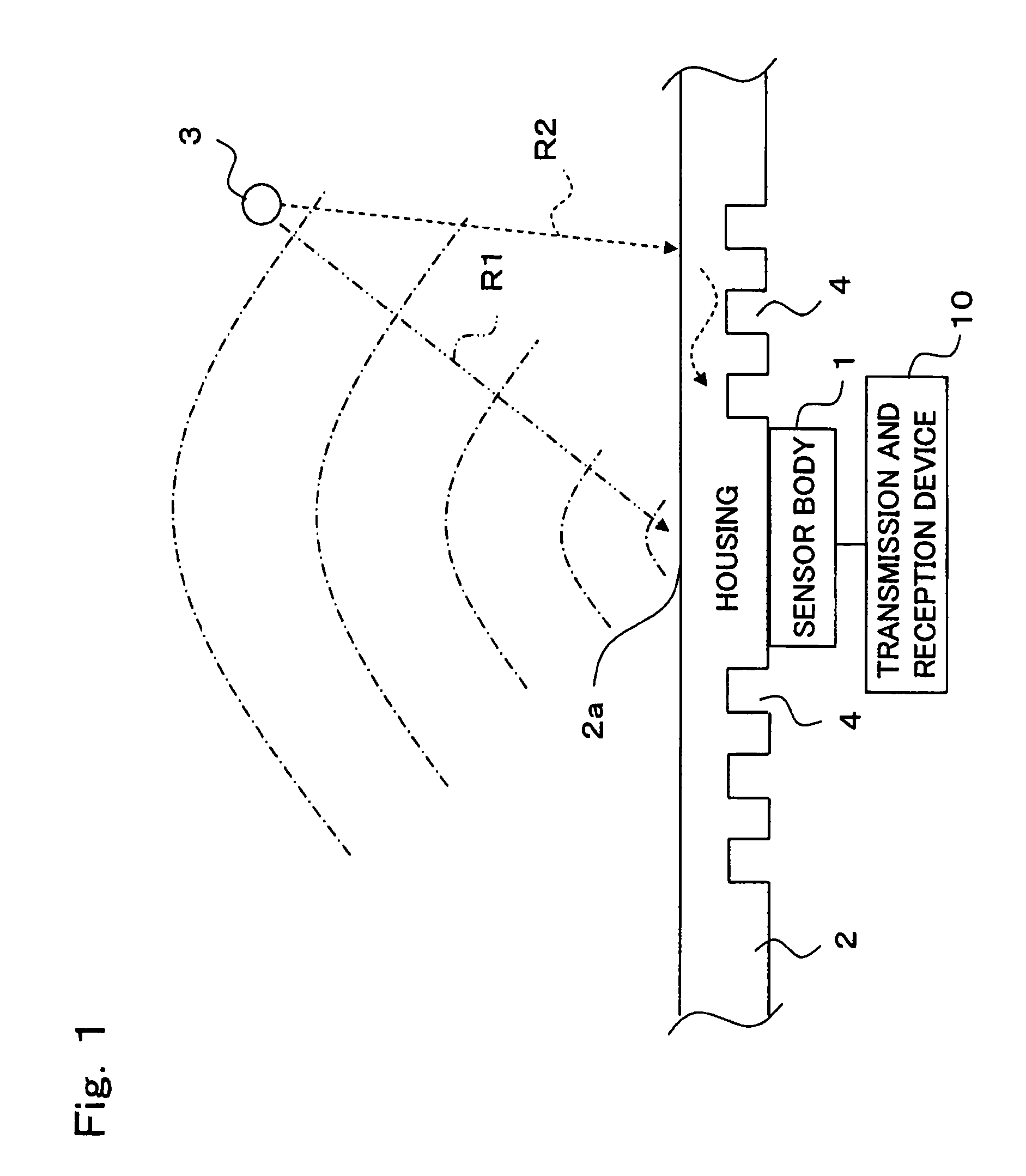
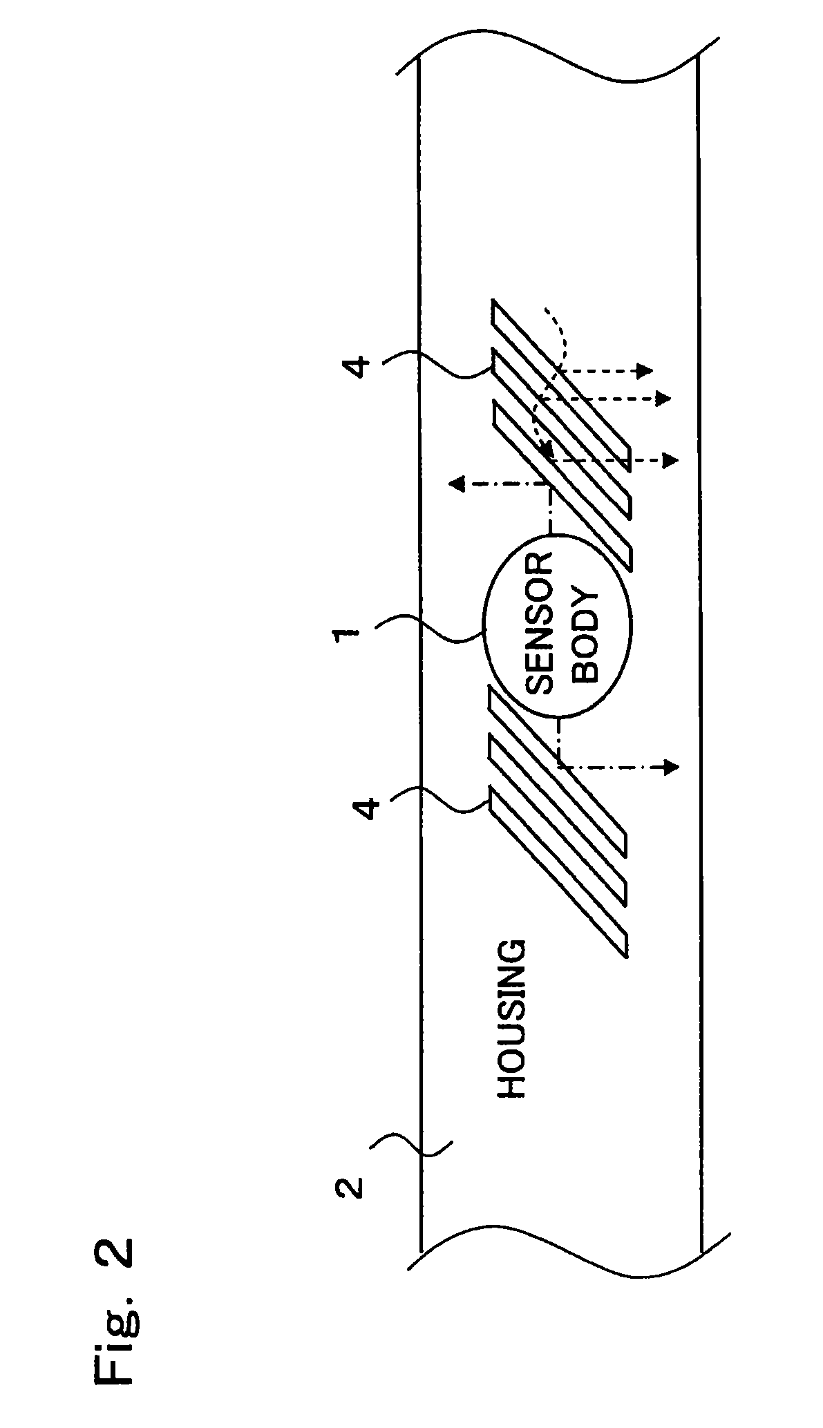
[0036]Hereinafter, reference will be made to an airborne ultrasonic sensor according to a first embodiment of the present invention, while referring to FIG. 1 through FIG. 6.

[0037]FIG. 1 is a plan view showing the airborne ultrasonic sensor according to the first embodiment of the present invention, and FIG. 2 is a front elevational view of the airborne ultrasonic sensor of FIG. 1.

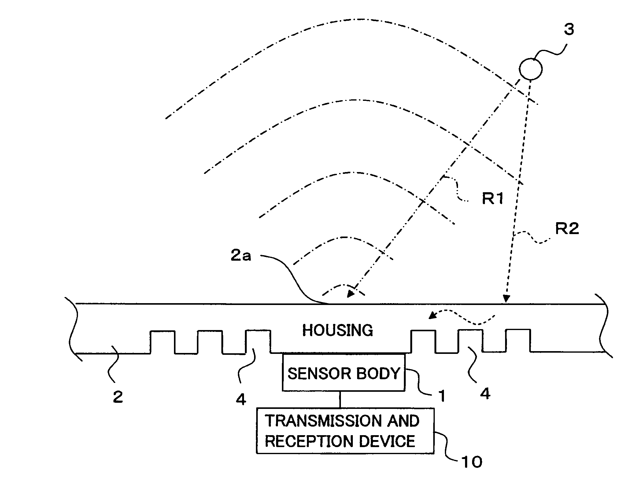
[0038]In addition, FIG. 3 and FIG. 4 are side elevational views, respectively, showing the reception states of the airborne ultrasonic sensor of FIG. 1, and illustrate the cases where a path R1 and a path R2 of reflection waves reflected from a reflection source 3 are respectively different from each other.

[0039]Here, note that in FIG. 3 and FIG. 4, in order to avoid complicatedness, the illustration of groove portions 4 is omitted for the purpose of simplification.

[0040]FIG. 5 is a front elevational view of another example of the airborne ultrasonic sensor of FIG. 1, and FIG. 6 is an explanatory view spec...


PUM


Abstract

An airborne ultrasonic sensor is obtained in which a sensor body and a housing have an integrated structure, and which can reduce spurious waves which propagate through the housing to arrive at the sensor body. The sensor is provided with the sensor body that radiates ultrasonic waves into air and at the same time receives reflected waves from a reflection source which exists in the air, a transmission and reception device that drives the sensor body and at the same time obtains a distance to the reflection source or a propagation speed of sound based on the reflected waves, and the housing that has the sensor body fixedly secured thereto with an integrated structure. The housing has groove portions which are different in acoustic impedance from their surroundings. The groove portions are arranged obliquely regarding either one of a horizontal direction or a vertical direction of the sensor body.

Description

TECHNICAL FIELD[0001]The present invention relates to an airborne ultrasonic sensor which radiates ultrasonic waves into the air and receives reflected waves from a reflection source (object) which exists in the surroundings, whereby it obtains the distance to the reflection source or the propagation speed of sound in the surroundings. In particular, the invention relates to a technique for reducing spurious waves which propagate through a housing with the body of the sensor mounted thereon, and which arrives at the body of the sensor.BACKGROUND ART[0002]In general, an airborne ultrasonic sensor is a device that serves to transmit ultrasonic waves into the air and receive the ultrasonic waves which have been reflected by an object, wherein it is applied to a variety of kinds of fields such as one for vehicle mounting, etc.[0003]First, as a conventional device, there has been proposed an obstacle detection device for mounting on a vehicle, which is provided with an airborne ultrasoni...

Claims


Application Information

Patent Timeline
Patent Type & Authority Patents(United States)
IPC IPC(8): G01H5/00G01S7/521G01S15/93G01S15/931
CPCG01S7/521G01S2015/938G01S15/931
Inventor KIMURA, TOMONORIIBATA, KOJIINOUE, SATORU
Owner MITSUBISHI ELECTRIC CORP
Learn More