
Signal receiving device, control method of signal receiving device, and optical communication system

A technology of signal receiving equipment and control methods, applied in optical fiber transmission, optical fiber radio, sustainable communication technology, etc., can solve problems such as signal stability control at difficult receiving ends, improve transmission performance and reliability, and increase optical signal reception The effect of dynamic range

Active Publication Date: 2021-07-09
BEIJING UNIV OF POSTS & TELECOMM
View PDF3 Cites 0 Cited by
  • Summary
  • Abstract
  • Description
  • Claims
  • Application Information

AI Technical Summary

Problems solved by technology

[0004] Therefore, the technical problem to be solved by the present invention is to overcome the defect in the prior art that it is difficult to realize stable control of the signal at the receiving end, thereby providing a signal receiving device, a control method for the signal receiving device, and an optical communication system

Method used


Image

  • Signal receiving device, control method of signal receiving device, and optical communication system
  • Signal receiving device, control method of signal receiving device, and optical communication system
  • Signal receiving device, control method of signal receiving device, and optical communication system

Examples


Embodiment Construction

[0025] The technical solutions of the present invention will be clearly and completely described below in conjunction with the accompanying drawings. Apparently, the described embodiments are some of the embodiments of the present invention, but not all of them. Based on the embodiments of the present invention, all other embodiments obtained by persons of ordinary skill in the art without making creative efforts belong to the protection scope of the present invention.

[0026] In the description of the present invention, it should be noted that the terms "center", "upper", "lower", "left", "right", "vertical", "horizontal", "inner", "outer" etc. The indicated orientation or positional relationship is based on the orientation or positional relationship shown in the drawings, and is only for the convenience of describing the present invention and simplifying the description, rather than indicating or implying that the referred device or element must have a specific orientation, ...


PUM


Abstract

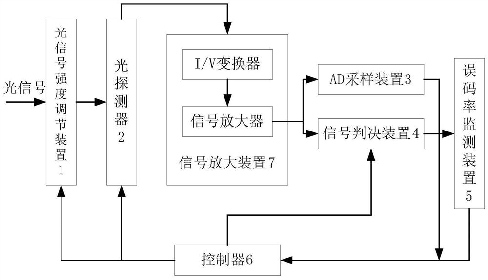
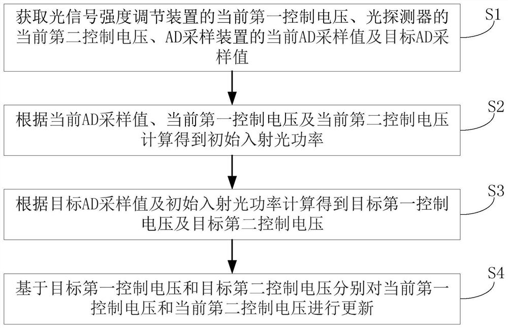
The invention provides a signal receiving device, a control method of the signal receiving device and an optical communication system, and the control method of the signal receiving device comprises the steps: obtaining a current first control voltage of an optical signal intensity adjustment device, a current second control voltage of an optical detector, and a current AD sampling value and a target AD sampling value of an AD sampling device; calculating initial incident light power according to the current AD sampling value, the current first control voltage and the current second control voltage; calculating a target first control voltage and a target second control voltage according to the target AD sampling value and the initial incident light power; and respectively updating the current first control voltage and the current second control voltage based on the target first control voltage and the target second control voltage. By implementing the invention, the self-adaptive control and optimization of the received signal are realized, and the transmission performance of an optical communication system and the stability and reliability of communication are improved.

Description

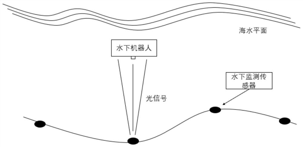
technical field [0001] The invention relates to the field of underwater wireless optical communication, in particular to a signal receiving device, a control method of the signal receiving device and an optical communication system. Background technique [0002] Underwater wireless optical communication is an underwater high-speed communication method. This communication method requires the transmitting end to modulate the data information into an optical signal, and the detector at the receiving end detects the optical signal, and converts the optical signal carried according to the change of light intensity into Data information, to complete the reception, detection and demodulation of data information. [0003] However, due to the complex underwater channel conditions, affected by factors such as platform vibration, water flow, and scattering particles, the transmitter and receiver cannot maintain a stable position, the attenuation of the wireless optical link is constant...

Claims


Application Information

Patent Timeline
IPC IPC(8): H04B10/2575H04B10/54
CPCH04B10/2575H04B10/54Y02D30/70
Inventor 高冠军宁杰刘涛吕沛豪张家梁
Owner BEIJING UNIV OF POSTS & TELECOMM
Learn More