Centrifugal pump

a centrifugal pump and centrifugal pump technology, applied in the direction of propellers, propulsive elements, water-acting propulsive elements, etc., can solve the problems of affecting lubrication, and achieve the effects of reducing the stress on the shaft seal, facilitating modification, and substantially shortening the dry running period

Active Publication Date: 2014-10-28
ROLLS ROYCE SOLUTIONS GMBH
View PDF4 Cites 0 Cited by
  • Summary
  • Abstract
  • Description
  • Claims
  • Application Information

AI Technical Summary

Benefits of technology

[0010]The inventors have also found that it is possible to avoid such unfavorable operating conditions or at least shorten them by providing on the seal carrier at a surface facing the impeller wheel a guide structure by which flow medium can be conducted from a radially outer area to the radially inner area when the impeller wheel rotates during operation of the pump. Although, with the rotation of the shaft carrying the rotor the liquid flow medium is driven to the radially outer area of the pump housing by the centrifugal forces, part is returned to the radially inner area by the guide structure. The guide structure is in accordance with the invention formed by an axially projecting guide surface which extends inclined against the direction of rotation of the impeller during operation of the pump. The guide structure causes a distribution of the flow medium carried along by the impeller so as to be guided in a direction opposite to the centrifugal forces that is from the radially outer area toward the radially inner area. In order to make this effect as advantageous as possible, it is further provided that the guide structure surface, that is essentially a limit contour between the guide surface and the surface area, extends from the radially outer area to the radially inner area.
[0012]The area is in particular part of a front side of the seal carrier facing the pumping chamber wherein the front side is arranged opposite a backside of the impeller facing away from the pumping chamber. The outer radial area and the inner radial area are advantageously areas of an annular chamber which is disposed between the seal carrier and the impeller and through the innermost radial area of which the drive shaft extends. The invention has been found to be particularly advantageous for a centrifugal pump in the form of a radial pump or a semi-axial pump. Herein, the pumping takes place from a suction side of the pumping chamber to a pressure side of the pumping chamber. The suction side of the pumping chamber is herein always at an inner radial area of the pumping chamber whereas the pressure side of the pumping chamber is always at the radially outer area of the pumping chamber. In connection with radial pumps or semi-axial pumps, the embodiment of the invention described above has been found to be particularly helpful and effective.
[0015]In a particularly preferred embodiment of the invention, the guide structure is in the form of a protruding deflector structure. Preferably, the deflector structure is formed by the side surface of a rib, a web or a similar structure. Basically any shape may be provided for the guide surface such as a shovel, a flag, a protrusion or other raised area with a suitably curved guide surface; it is however advantageous if the deflection surface is a side surface of a rib or web or another projection which can be formed comparably easily. An existing centrifugal pump can be easily modified by the installation of a rib or web to form a deflection area. Especially during startup operation of the centrifugal pump, in this way, liquid flow medium is conducted from the radially outer area to the radially inner area for the lubrication and cooling of the shaft seal. In this way, the shaft seal stresses are advantageously reduced in that the dry running period is substantially shortened. In addition, a cooling effect is obtained and the temperature at the shaft seal, in particular in the sealing gap of the slide ring seal is more uniform. Tensions within the components of the shaft seal are effectively suppressed.
[0016]Overall, it has been found to be advantageous if the height of the deflection surface area corresponds essentially to the height of a part of the shaft seal. Such adjustment of the height of the deflection surface to the height of a part of the shaft seal—in particular the slide ring and / or the counter ring of a slide ring seal—results in a comparably good supply of flow medium to the shaft seal, in particular a slide ring seal. In particular, with the tuning of the height of the deflection surface and a part of the shaft seal in accordance with the above-described embodiment, the flow medium is conducted—as seen in axial direction—practically to the level of the seal gap toward the shaft seal and a flow pressure of the cooled flow medium is comparatively high at a seal gap inlet openings. In particular, the flow medium can be conducted thereby directly into the seal gap. This results in a further improved, particularly effective and rapid cooling and lubricating effect of the cooling medium in the seal gap of the shaft seal. This concept can be realized in that a level of the projecting deflecting area corresponds essentially to the level of a slide ring of a slide ring seal. Preferably, a countering of the slide ring seal is included in the seal carrier.
[0020]For an increased effectiveness of the concept according to the invention, an inclination of the guide surface can be established which extends at least partially at an angle with respect to a rotational direction of an impeller. The inclination is indicated here with respect to a horizontal radial line; it may be for example an angle between 90° and 0°. At 90°, the guide area extends normal to the rotational direction of the impeller. An angle between 15° and 75°, and particularly between 30° and 60° has been found to be particularly effective. With a decreasing inclination angle, the guide area extends comparably flat with regard to the impeller with a rotating seal ring. A small angle may provide for less friction and will provide, particularly at higher speeds, still for an effective redirecting of the flow medium toward the shaft seal. This is particularly true for a contour curve which extends along a tangent to the shaft circumference.

Problems solved by technology

It has been found that the formation of such an air pocket in the area of the shaft seal while it is already rotating detrimentally affect the lubrication and / or cooling of the shaft seal by the liquid flow medium.

Method used


Image

  • Centrifugal pump
  • Centrifugal pump
  • Centrifugal pump

Examples


first embodiment

[0044]FIG. 3 shows in an axial view the front side 25 of a seal carrier 15.1 the surface F and the drive shaft 13 of a radial pump.

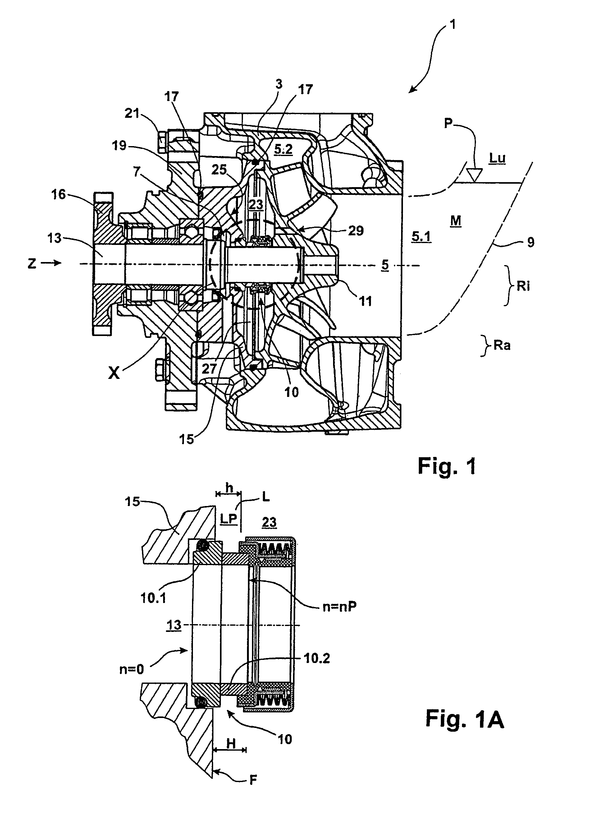
[0045]On the front side 25 of the seal ring carrier 15.1, there is a guide structure L which is formed as a single web 41 on the surface F. The web H includes as side surface a deflecting area LP protruding from the side surface. Such a deflective surface shown already in the detail X of FIG. 1A has a height h which corresponds about to the height dimension 11 of the slide ring 10.2 of the slide ring seal 10 and has the advantages mentioned earlier.

[0046]The deflecting surface LP has a contour which extends from a radially outer area Ra of the annular chamber 23 to a radially inner area Ri transversely to a radius R which extends from the center point of the drive shaft 13.

[0047]As apparent from FIG. 3, the deflecting surface area LP of the web 41 extends herewith transversely to the direction of rotation D of the flow medium M in the annular chamber 23 ...

second embodiment

[0049]FIG. 4 shows a variation of a seal carrier 15.2 for a radial pump with a guide structure L. The guide structure L is in the form of a web or rib 51 and has a deflecting surface area LP similar to the deflecting area LP of the seal carrier 15.1 of FIG. 3. The contour of the deflecting area LP is mostly curved but otherwise also extends at an inclination with respect to the radius R of an annular chamber, wherein an extrapolation of the contour extends toward the center of the drive shaft 13. In addition, the deflection area L has an inclination also in a direction transverse to the direction of rotation D of the rotating impeller 11. In this arrangement, furthermore, the inclination is increased at the inner radial area Ri that is adjacent the slide ring seal 10 at the drive shaft 13. At the outer radial area Ra, the inclination is smaller at the peripheral surface area F. The flow direction S is also in this case symbolically indicated by arrows.

third embodiment

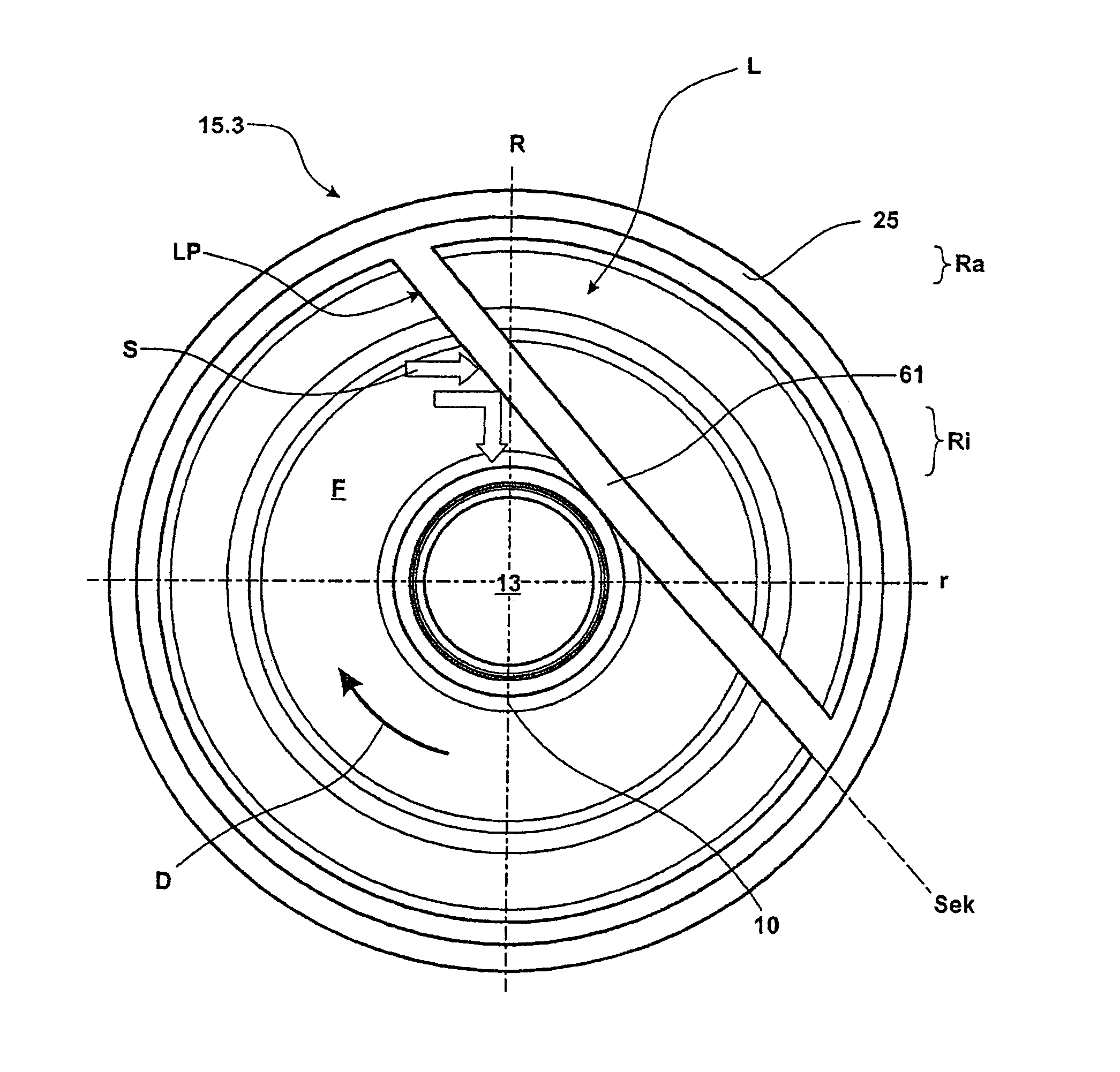
[0050]FIG. 5 shows a further variation of a seal carrier 15.3 for a radial pump. It includes a seal carrier 15.3 wherein the guide structure L is provided by a rib 61 which extends along a straight line and has a deflection surface area LP in the form of a side surface of the web or rib 61. The deflection surface area LP projects from the surface 7 and provides in principle for a flow as it is shown in connection with FIG. 3, that is, a flow S from an outer radial area Ra to an inner radial area Ri. The contour of the deflection surface area LP extends mainly along a secant Sek for the surface area F. The secant Sek extends tangential to the slide ring seal 10 or, respectively, tangential to the circumference of the drive shaft 13. Finally, the web 61 extends throughout along the length of the secant Sek through the area F at the front side 25 of the seal carrier 15. While the web 41, 51 is limited on the surface area F to an area of a radius R, the web 61 and the section A of FIG. ...


PUM


Abstract

In a centrifugal pump, in particular a radial or semi-axial pump including a housing with a pump chamber and a dry chamber, a drive shaft rotatably supported in the housing and connected to an impeller for pumping a liquid flow medium disposed in the pump chamber and a shaft seal arranged in an inner radial area for sealing the dry space with respect to the flow medium, a seal carrier is provided with a guide structure by which fluid flow medium is conducted from an outer radial area to an inner radial area for directing flow medium into the seal for lubrication and cooling of the seal.

Description

BACKGROUND OF THE INVENTION[0001]The invention relates to a centrifugal pump, in particular, a radial pump or a semi-axial pump including a housing with a pumping space and a dry space, a drive shaft rotatably supported in the housing and an impeller wheel firmly connected to the drive shaft for pumping a flow medium in the pumping space, and a shaft seal arranged in an inner radial area for sealing the dry space with respect to the flow medium wherein at least a part of the shaft seal is held in position by a seal cover connected to the housing.[0002]A centrifugal pump of this type for pumping a liquid flow medium is used in particular for pumping sea water in ships. In such an application, a centrifugal pump of the type referred to above is exposed to comparably high stresses. Still a reliable operation is necessary even after an extended shutdown.[0003]It is a problem with centrifugal pumps for pumping a liquid flow medium that a shaft seal during initial operation of the pump is...

Claims


Application Information

Patent Timeline
Patent Type & Authority Patents(United States)
IPC IPC(8): F04D29/10F01D11/00
CPCF04D29/126
Inventor REISCHMANN, WOLFGANGVAULIN, ALEXEJRUCK, JOACHIM
Owner ROLLS ROYCE SOLUTIONS GMBH
Why Eureka
Try Eureka