Electrical connector having means to prevent terminal spaces falling apart from a circuit board

a technology of electrical connectors and terminal spaces, which is applied in the direction of coupling devices, coupling devices, and coupling devices with two-part components, etc., can solve the problems of circuit board p deformation, electrical contact stability, and defective electrical contact between the circuit board p and the connector terminal, so as to ensure the contact stability and prevent the reduction of the contact load

Inactive Publication Date: 2014-11-04
DAIICHI SEIKO CO LTD
View PDF10 Cites 4 Cited by
  • Summary
  • Abstract
  • Description
  • Claims
  • Application Information

AI Technical Summary

Benefits of technology

[0011]In view of the above-mentioned problems in the conventional card edge connector, it is an object of the present invention to provide an electric connector which is capable of ensuring the contact stability by preventing reduction in a contact load at which a connector terminal makes contact with a circuit board.
[0013]The electrical connector in accordance with the present invention is designed to include the structure for preventing the terminal spaces and the circuit board from falling apart from each other. The structure is formed on or at a sidewall or opposite sidewalls of the sheath and a partition wall or partition walls facing the sidewall or the opposite sidewalls of the sheath. The structure ensures that a compressive force exerted by the connector terminal on the connector housing acts not only on a connector housing at a rear of the connector terminal, but also on a partition wall of the connector housing. Thus, a compressive force exerted by the connector terminal is dispersed, and hence, a compressive force exerted on a connector housing at a rear of the connector terminal is reduced, ensuring it possible to prevent a gap between the terminal space and the circuit board from being widened. Furthermore, since it is possible to prevent a gap between the terminal space and the circuit board from being widened, it is also possible to prevent fluctuation in a contact load at which a connector terminal makes contact with a circuit board, ensuring that a contact resistance can be kept stable.
[0024]In another aspect of the present invention, there is provided a connector housing having a slot into which a circuit board is to be inserted, a plurality of connector terminals being to be inserted into the connector housing, the connector housing including terminal spaces into which the connector terminals are inserted, and partition walls partitioning the terminal spaces from adjacent ones, the connector terminals each including a sheath to be inserted into one of the terminal spaces, and a resilient contact making electrical contact with the circuit board, the sheath being formed on at least one of opposite sidewalls thereof with a convex or a concave, the partition wall or partition walls facing the at least one of opposite sidewalls of the sheath being formed with a concave or a convex for preventing the terminal spaces and the circuit board from falling apart from each other.
[0027]Since the electrical connector in accordance with the present invention is able to reduce a compressive force exerted on a connector housing at a rear of a connector terminal, it is possible to prevent a gap between a terminal space and a circuit board from being widened. Thus, since the electrical connector in accordance with the present invention can prevent a gap between a terminal space and a circuit board from being widened, it is also possible to prevent a contact load at which a connector terminal makes contact with a circuit board from being reduced, maintaining stability of a contact between a connector terminal and a circuit board.

Problems solved by technology

The lowered contact load brings problems that the stability in electrical contact between the card edge connector 10x and the circuit board P is degraded, specifically, the circuit board P is easily taken off the connector housing 110x, and / or oscillation brings the defectiveness in electrical contact between the circuit board P and the connector terminal 120x.

Method used


Image

  • Electrical connector having means to prevent terminal spaces falling apart from a circuit board
  • Electrical connector having means to prevent terminal spaces falling apart from a circuit board
  • Electrical connector having means to prevent terminal spaces falling apart from a circuit board

Examples


first embodiment

[0044]An electrical connector (hereinafter, called “a card edge connector”) in accordance with the first embodiment of the present invention is described hereinbelow with reference to the drawings.

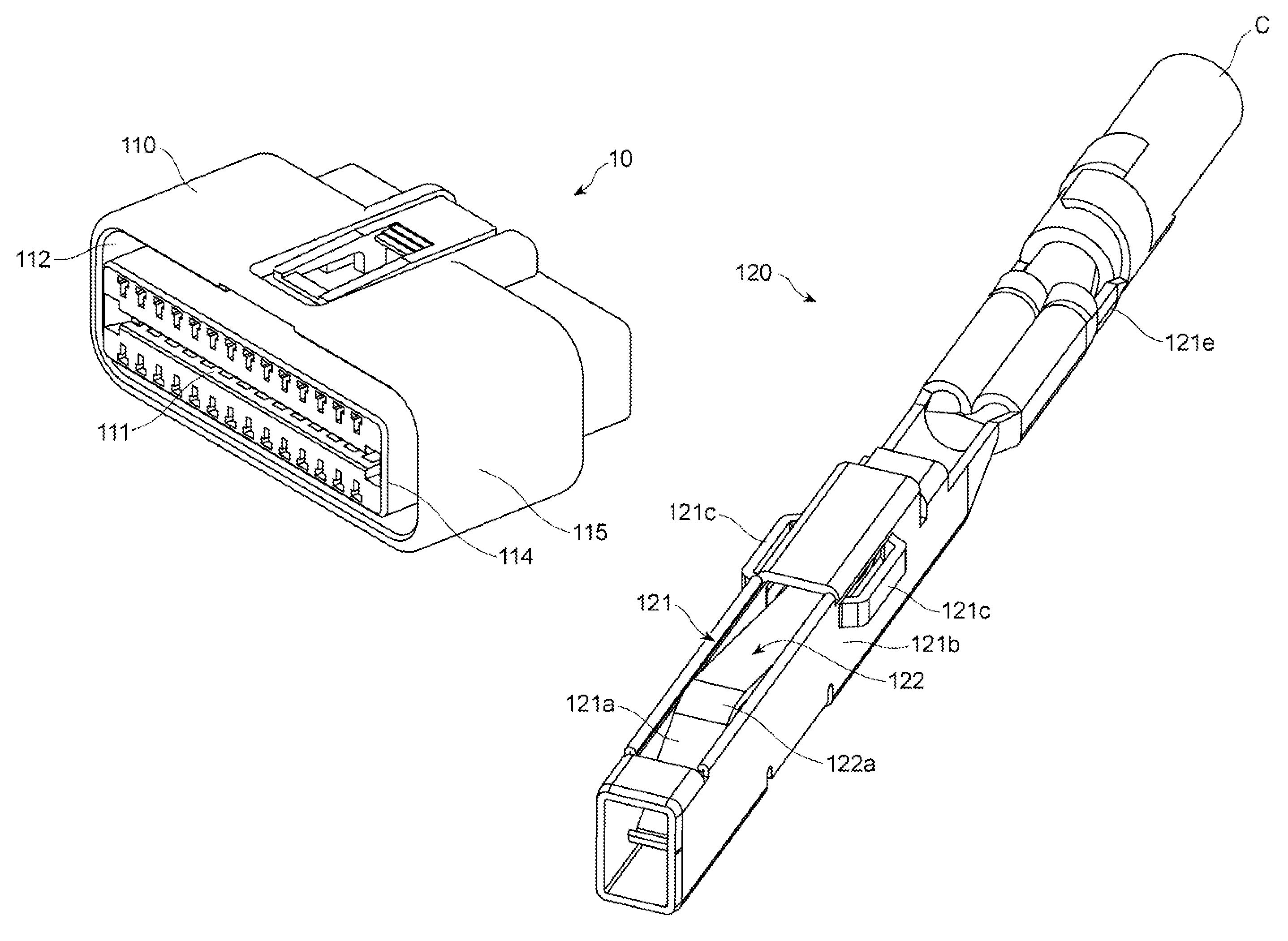
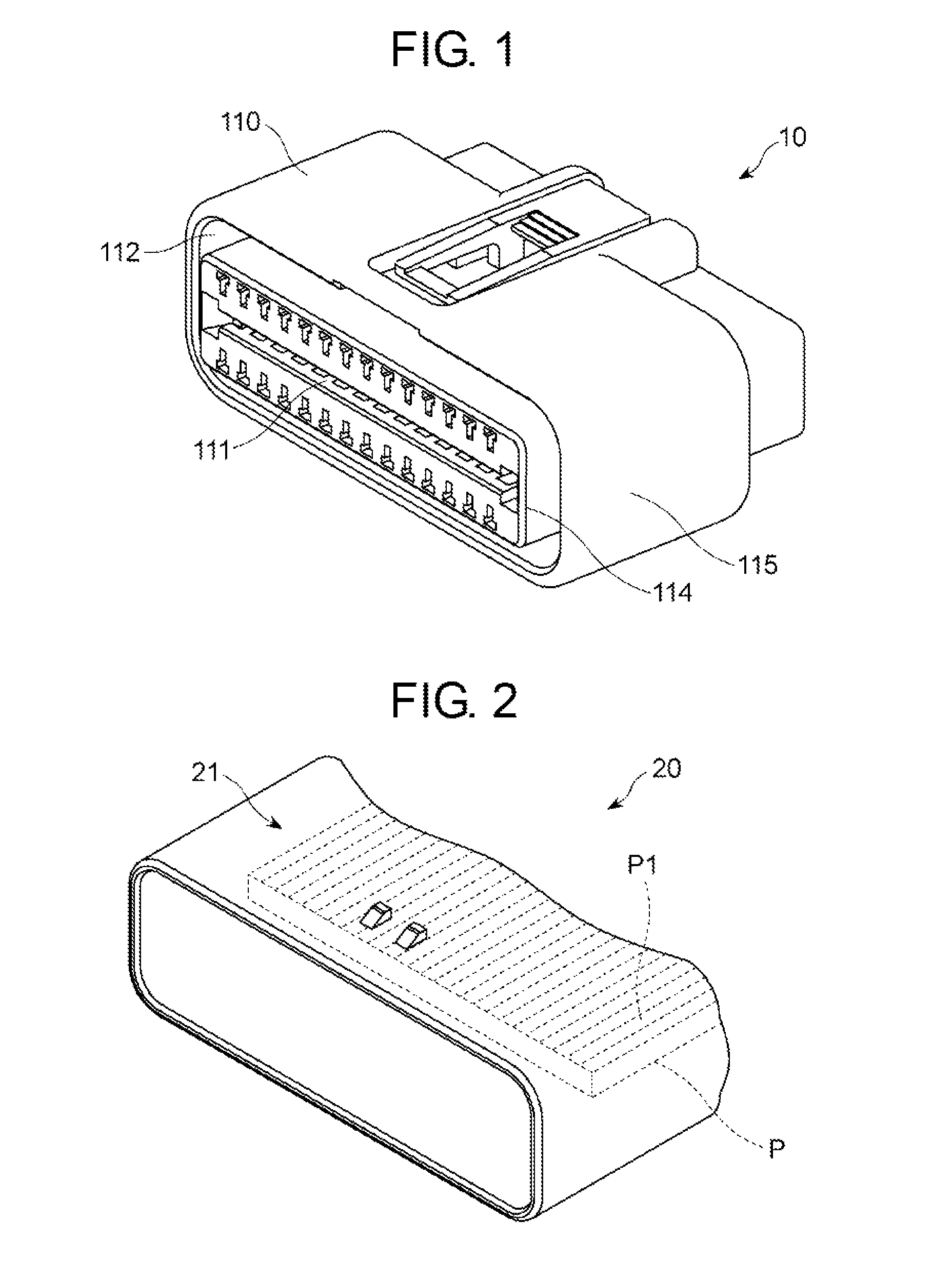
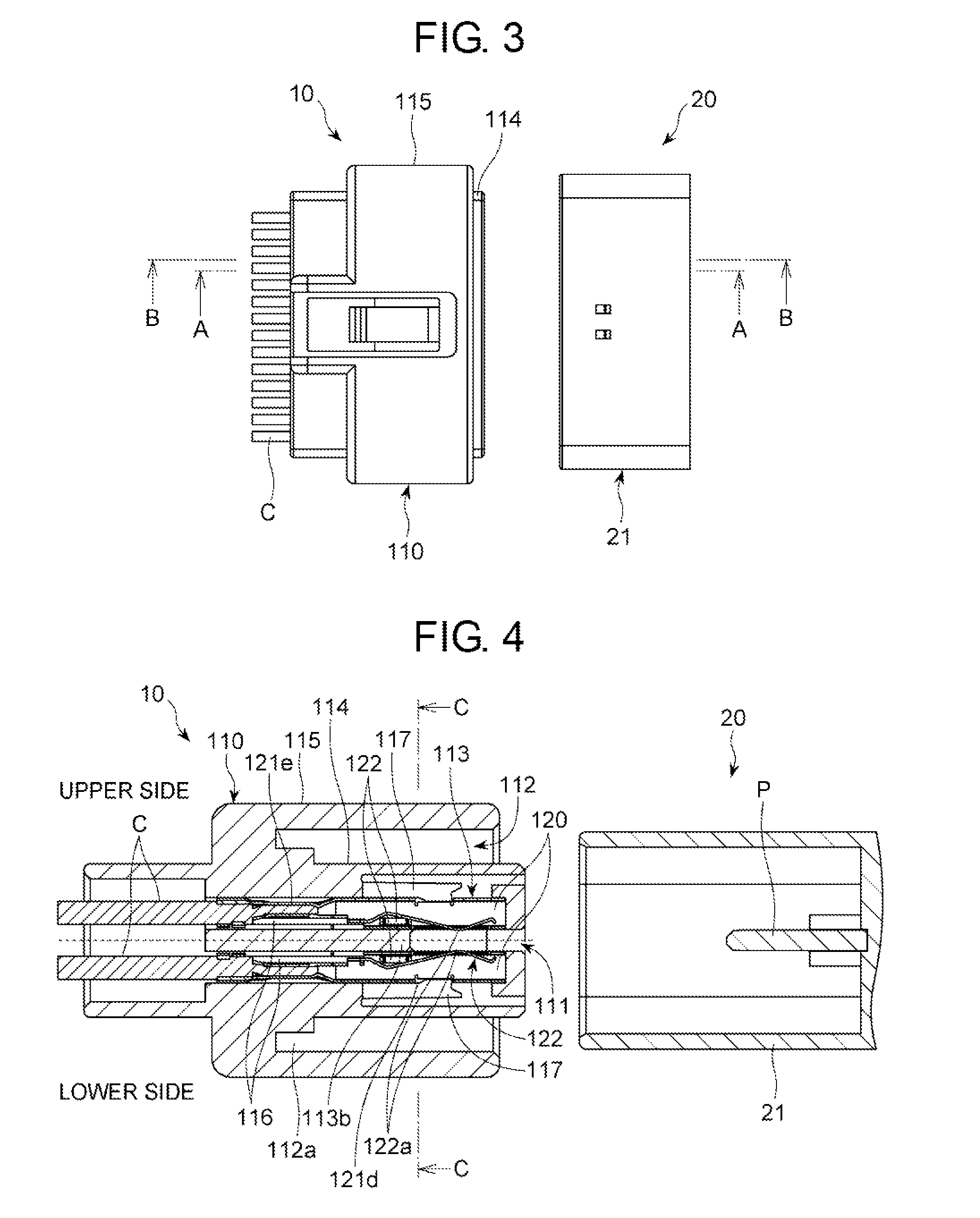
[0045]As illustrated in FIGS. 1 to 3, when a connector 20 equipped in a metal case including therein electronic devices used for an automobile is inserted into a card edge connector 10 in accordance with the first embodiment of the present invention, the card edge connector 10 electrically connects the electronic devices to cables C electrically connected to the card edge connector 10.

[0046]As illustrated in FIGS. 4 to 7, the card edge connector 10 includes a connector housing 110 and a plurality of connector terminals 120.

[0047]The connector housing 110 is a resin-molded product. The connector housing 110 is designed to include a slot 111 into which a circuit board P of the connector 20 is to be inserted, a circular slot 112 into which a connector housing 21 of the connector 20 is to be i...

second embodiment

[0075]FIG. 10 is a cross-sectional view of a card edge connector in accordance with the second embodiment of the present invention.

[0076]Parts or elements that correspond to those of the card edge connector in accordance with the first embodiment have been provided with the same reference numerals, operate in the same manner as corresponding parts or elements in the first embodiment, unless explicitly explained hereinbelow, and are not explained in detail.

[0077]In the card edge connector in accordance with the second embodiment, the linear grooves 116 are formed at opposite sidewalls of the partition wall 113a at a different height from each other, as illustrated in FIG. 10. Specifically, the linear groove 116 formed at a left sidewall of a certain partition wall 113a is situated lower than the linear groove 116 formed at a right sidewall of the partition wall 113a, for instance. In other words, the linear groove 116 formed at a left sidewall of a certain partition wall 113a is situ...

third embodiment

[0080]FIG. 11 is a cross-sectional view of a card edge connector in accordance with the third embodiment of the present invention.

[0081]Parts or elements that correspond to those of the card edge connector in accordance with the first embodiment have been provided with the same reference numerals, operate in the same manner as corresponding parts or elements in the first embodiment, unless explicitly explained hereinbelow, and are not explained in detail.

[0082]In the card edge connector in accordance with the third embodiment, a combination of the linear grooves 116 and the projections 121c in a first terminal space 113 is located at a different height from a height of a combination of the linear grooves 116 and the projections 121c in a second terminal space 113 located adjacent to the first terminal space 113.

[0083]The projections 121c of the sheath 121 are formed in accordance with the linear grooves 116. Accordingly, the sheath 121 corresponding to the first terminal space 113 i...


PUM


Abstract

An electrical connector includes a connector housing having a slot into which a circuit board is to be inserted, and a plurality of connector terminals to be inserted into the connector housing. The connector housing includes terminal spaces into which the connector terminals are inserted, and partition walls partitioning the terminal spaces from each other. The connector terminals each include a sheath to be inserted into one of the terminal spaces, and a resilient contact making electrical contact with the circuit board. The electrical connector includes a convex portion and a concave portion for preventing the terminal spaces and the circuit board from falling apart from each other. The convex portions can be formed on opposite sidewalls of the sheath, and the concave portions can be formed at the partition walls.

Description

BACKGROUND OF THE INVENTION[0001]1. Field of the Invention[0002]The invention relates to an electric connector in which, when a circuit board having circuit terminals is inserted into a slot formed at the electric connector, connector terminals make electrical contact with the circuit terminals.[0003]2. Description of the Related Art[0004]An example of an electric connector which is called a card edge connector and into which a circuit board on which circuit terminals are formed at an edge is inserted is disclosed in Japanese Utility Model Application Publication No. H5 (1993)-84053, for instance.[0005]In the electric connector disclosed in the publication, a connector housing is designed to have therein terminal spaces vertically formed by two stages, and a slot into which a circuit board is to be inserted, extending from a front of the connector housing and between the upper and lower terminal spaces. Connector terminals are inserted into the upper and lower terminal spaces. Each ...

Claims


Application Information

Patent Timeline
Patent Type & Authority Patents(United States)
IPC IPC(8): H01R13/514H01R13/40H01R12/72H01R13/422
CPCH01R12/721H01R13/4226H01R13/40
Inventor ENDO, TAKAYOSHIMATSUSHITA, DAISUKE
Owner DAIICHI SEIKO CO LTD
Why Eureka
Try Eureka