Resistance testing equipment

A resistance test and voltage test technology, applied in the direction of measuring resistance/reactance/impedance, measuring devices, measuring electrical variables, etc., can solve the problems of uncertainty in the use of the test object, the cost cannot be reduced, and the test object is destroyed.

Pending Publication Date: 2019-06-11
川源科技(苏州)有限公司
View PDF9 Cites 0 Cited by
  • Summary
  • Abstract
  • Description
  • Claims
  • Application Information

AI Technical Summary

Problems solved by technology

[0005] CN207528818U also discloses a kind of resistance test equipment, and the resistance testers disclosed by CN204903649U and CN207528818U are all offline tests, and not only will the test object be damaged during the sample selection test, so that it cannot be used after the test, so that the use of the test object still has uncertainty And the cost can not be reduced, and only for a small part of the selected test object, but not all areas or designated areas, it is a solution for repeated and tedious tests to collect multi-point data
In addition, the industry currently does not test all areas or designated areas of battery pole pieces, conductive thin layers (such as copper and aluminum foil and other metals, alloys, etc.), non-conductive thin layers (such as polymer thin layers, etc.) (intermittent test) or real-time continuous and simple test solutions, therefore, it is imminent to develop resistance testing equipment with real-time measurement and online measurement functions

Method used


Image

  • Resistance testing equipment
  • Resistance testing equipment
  • Resistance testing equipment

Examples


Embodiment 1

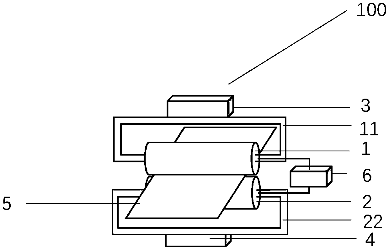
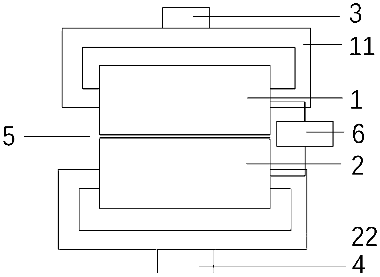
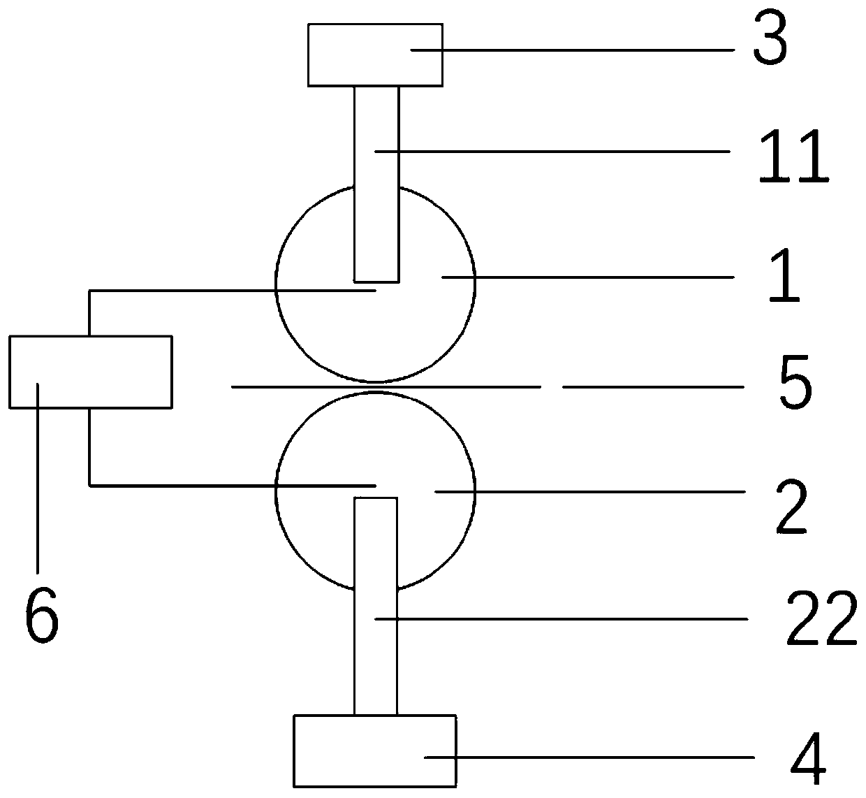
[0067] Please refer to Figure 1 to Figure 3 , figure 1 It is a schematic diagram of a three-dimensional structure of a specific embodiment of the resistance testing equipment provided by the present invention; figure 2 It is a schematic front view of a specific embodiment of the resistance testing equipment provided by the present invention; image 3 It is a schematic diagram of a right side view of a specific embodiment of the resistance testing equipment provided by the present invention. The contact interface between the first pressure member 1 and the first supporting member 2 is a line interface. In the present invention, the contact interface when the first pressure member 1 is in contact with the first support member 2 can be a line-line interface, or a point-point interface or a point-line interface, and the line-line interface or point-point interface or point-line interface can be respectively 1 or more.

[0068] like Figure 1 to Figure 3 As shown, the presen...

Embodiment 2

[0089] Please refer to Figure 4 to Figure 5 , Figure 4 It is a schematic diagram of the three-dimensional structure of another specific embodiment of the resistance testing equipment provided by the present invention; Figure 5 It is a schematic front view of another specific embodiment of the resistance testing equipment provided by the present invention; Image 6 It is a schematic diagram of the right side view of another embodiment of the resistance testing equipment provided by the present invention.

[0090] The difference from Embodiment 1 is that the first pressure member 1 and the first supporting member 2 are in indirect contact through the test object 5, and the contact interface during contact is two line-line interfaces. Therefore, the first pressure component 1 and the first support component 2 are two, and as in Embodiment 1, they are independently installed on the first pressure component support frame 11 and the first support component support frame 22 res...

Embodiment 3

[0097] Please refer to Figure 7 to Figure 8 , Figure 7 It is a schematic diagram of the three-dimensional structure of yet another specific embodiment of the resistance testing equipment provided by the present invention; Figure 8 It is a schematic diagram of the right side view of yet another embodiment of the resistance testing equipment provided by the present invention;

[0098] The difference from Embodiment 1 is that the specific shapes of the first pressure member 1 and the first support member 2 are different, they are all spherical, and the first pressure member 1 and the first support member 2 are in indirect contact through the test object 5, and the contact When the contact interface is a point interface; at the same time, the resistivity of the first pressure member material and the first support member material is 6.5×10- 8 Ω·m, the surface hardness is 800HV, the roughness Ra is 0.4um; the others are the same.

[0099] The method of using the resistance tes...


PUM

PropertyMeasurementUnit
Roughnessaaaaaaaaaa
Resistivityaaaaaaaaaa
Roughnessaaaaaaaaaa

Abstract

The invention discloses resistance testing equipment. The equipment comprises a first pressure part, a first supporting part, a pressure control device, a pressure sensor and a testing module, whereinthe first pressure part is positioned above the first supporting part and opposite to the first supporting part; a contact interface when the first pressure part is in contact with the first supporting part is a line-line interface, a point-point interface or a point-line interface; the pressure control device is connected with the first pressure part and / or the first supporting part; the pressure sensor is connected with the first pressure part and / or the first supporting part; the testing module is a resistance testing module, or a voltage testing module and / or a current testing module; andthe first pressure part and the first supporting part are connected with the resistance testing module, or the voltage testing module and / or the current testing module. The equipment is used for performing intermittent testing or real-time testing on all areas or designated areas of a test object.

Description

technical field [0001] The invention relates to the technical field of testing, in particular to resistance testing equipment for testing battery pole pieces, conductive thin layers (such as various metals such as copper and aluminum foils, alloys, etc.), and non-conductive thin layers (such as polymer thin layers, etc.). Background technique [0002] Lithium batteries are widely used due to their high volume-to-energy ratio, high weight-to-energy ratio, high voltage, low self-discharge rate, no memory effect, and long cycle life. It has never stopped, especially a lot of exploration and research have been carried out on improving the pole piece materials of lithium batteries. [0003] The electrode sheet resistance of a lithium battery is an important factor affecting the internal resistance, voltage, and self-discharge rate of the battery. Therefore, improving the electrode sheet resistance of a lithium battery is of great significance for increasing the energy of the batt...

Claims


Application Information

Patent Timeline
IPC IPC(8): G01R27/08G01R1/04
Inventor 李慧萍袁金春潘淑芳尧磊余海平
Owner 川源科技(苏州)有限公司
Why Eureka
Try Eureka