Centering for a TAA

a taa and centering technology, applied in the field of taa centering, can solve the problems of complex placement of stent-graft, high likelihood of asymmetric deployment of stent-graft,

Active Publication Date: 2014-11-04
MEDTRONIC VASCULAR INC
View PDF19 Cites 5 Cited by
  • Summary
  • Abstract
  • Description
  • Claims
  • Application Information

AI Technical Summary

Benefits of technology

[0016]By steering the delivery catheter to center the end of the catheter containing the stent-graft prior to deployment and simultaneously using tip capture to prevent uncontrolled outward bending of the proximal spring of the stent graft, the initial deployment of the stent-graft (the proximal edge of it stent graft material) is substantially orthogonal to the axial centerline of the curved vessel at the deployment location. As the initial deployment of the stent-graft is symmetric, the need to reposition the stent-graft after initial deployment may be avoided. Accordingly, the initially deployed stent-graft is accurately placed within the curved vessel and the need to deploy additional stent-grafts is eliminated.

Problems solved by technology

However, in complex vessels, e.g., in the aortic arch or other curved vessel, placement of the stent-graft is complicated by the tendency of the catheter to maintain a straight shape while the surround vessel curves.
This offset positioning (to the outer radius) of the distal tip of the delivery system combined with the effect blood flow forces have on the stent-graft as it is deployed, results in a high likelihood that the stent graft will be deployed asymmetrically.
To correct the initial asymmetrical deployment, the physician typically tries to reposition the stent-graft, which is generally undesirable (as vessel wall abrasion and more extensive injury may result) depending upon the particular stent graft and anatomical geometry involved.

Method used


Image

  • Centering for a TAA
  • Centering for a TAA
  • Centering for a TAA

Examples


Embodiment Construction

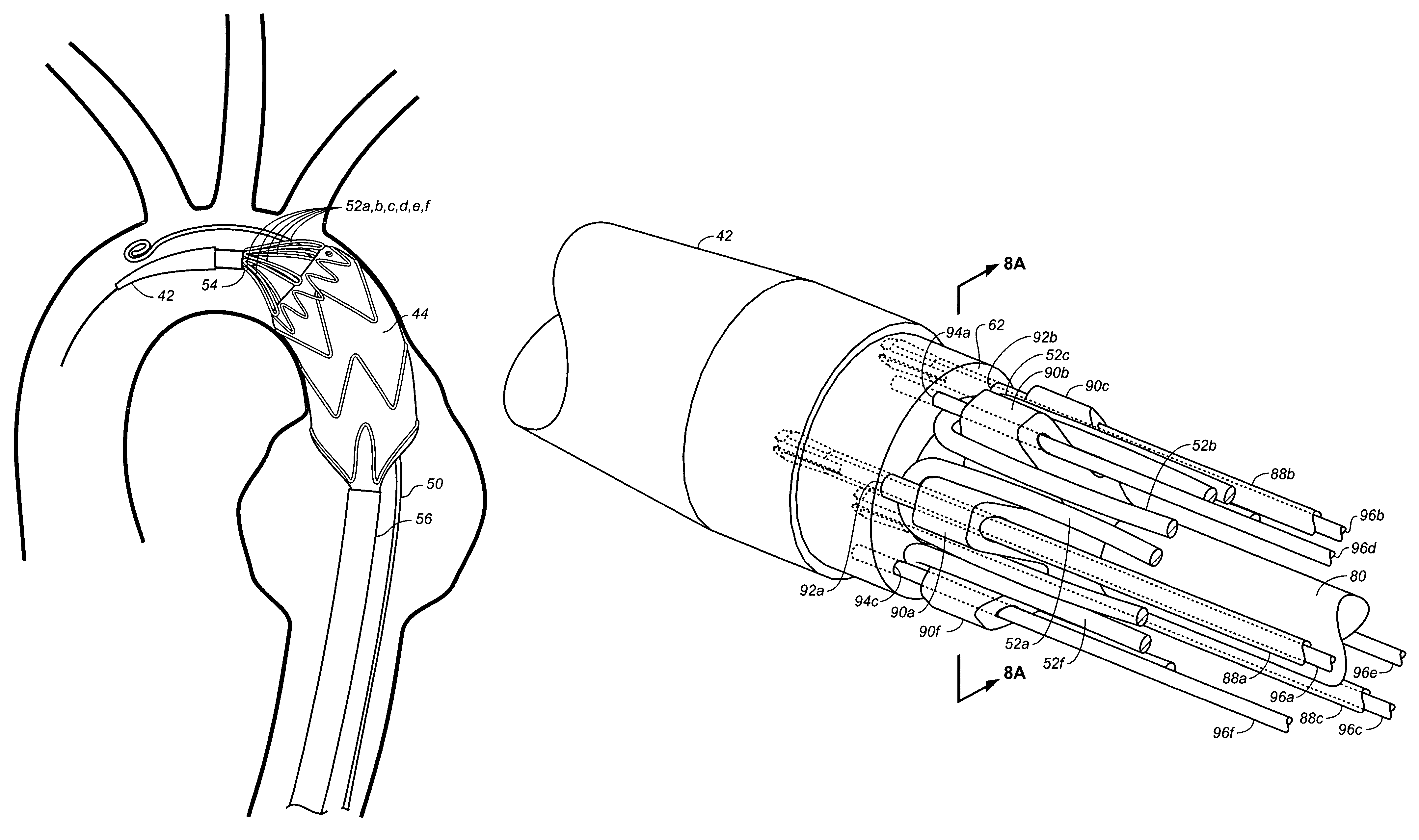
[0030]A steerable catheter with a integral tip release mechanism is described below. An aortic arch 30 containing a delivery catheter 40 (having a tip 42 and containing a stent graft 44) conforming to the outside radius of curvature 34 of the arch 33, is shown in FIG. 2A. Since the tip 42 of the deliver catheter 40 naturally lays along the outer radius of the arch away from the center of the vessel, a steering mechanism (later described) is used to move the tip of the tip 42 of the catheter and it's distal end 46 towards the center of the vessel (as shown by the moving arrow 48 showing the distal end 46 of the delivery catheter 40 being moved to the center of the vessel in FIG. 2B). Once moved to the center of the vessel and held there as shown in the dashed-line representation as shown in FIG. 2B, the sheath of the delivery system can be retracted to begin deployment of the stent graft 44. A contrast injection catheter 50 may be used to position the longitudinal position of the del...


PUM


Abstract

A stent graft is deployed by a steerable catheter delivery system having a integral tip capture release mechanism. The steering mechanism provides for a locked interference with a distal lock at the distal end of the delivery catheter. The configuration allows for selective circumferentially distributed release of one half or less of the number of crowns of a proximal spring which are captured by a tip capture mechanism so that new positioning of the stent graft can be verified and assured before full release of all proximal spring crowns is done. In this way, one or more steering elements of a catheter can be maintained in tension until catheter position is verified and acceptable stent graft position is achieved. This apparatus and method is particularly useful for deploying stent graft in curved passages such a thoracic aorta.

Description

FIELD OF THE INVENTION[0001]This invention relates generally to a steerable tip capture TAA delivery system used to deliver stents and stent grafts.BACKGROUND[0002]This invention relates generally to medical devices and procedures, and more particularly to a method and system of deploying stent-grafts in a vascular system.[0003]Prostheses for implantation in blood vessels or other similar organs of the living body are, in general, well known in the medical art. For example, prosthetic vascular grafts formed of biocompatible materials (e.g., Dacron® material or expanded, porous polytetrafluoroethylene (PTFE) tubing) have been employed to replace or bypass damaged or occluded natural blood vessels.[0004]A graft material supported by a framework is known as a stent-graft or endoluminal graft. In general, the use of stent-grafts for treatment or isolation of vascular aneurysms and vessel walls which have been thinned or thickened by disease (endoluminal repair or exclusion) is well know...

Claims


Application Information

Patent Timeline
Patent Type & Authority Patents(United States)
IPC IPC(8): A61F2/06A61F2/95A61F2/07A61M25/01A61M25/00A61F2/966
CPCA61F2002/9517A61M25/0147A61F2002/9665A61M2025/015A61F2002/9511A61F2/07A61F2/95A61M25/0082A61F2/9517
Inventor ARGENTINE, JEFFERY
Owner MEDTRONIC VASCULAR INC
Why Eureka
Try Eureka