
X-ray generator

a generator and x-ray technology, applied in the field of x-ray generators, can solve the problems of inability to achieve high-level x-ray focusing efficiency of x-ray conditioning elements, inability to effectively utilize large portion of x-ray generated from x-ray focal points f, and maintenance must be performed by the manufacturer of x-ray generators, so as to reduce the width of the anticathode housing space of the casing, reduce the distance, and reduce the distance from the x-ray

Inactive Publication Date: 2014-11-04
RIGAKU CORP
View PDF9 Cites 4 Cited by
  • Summary
  • Abstract
  • Description
  • Claims
  • Application Information

AI Technical Summary

Benefits of technology

[0016]The present invention was developed in view of the problems of the prior art described above, and an object of the present invention is to provide an X-ray generator whereby X-ray focusing efficiency of an X-ray conditioning element such as a monochromator can be enhanced without hindering the manual replacement of the electron gun.
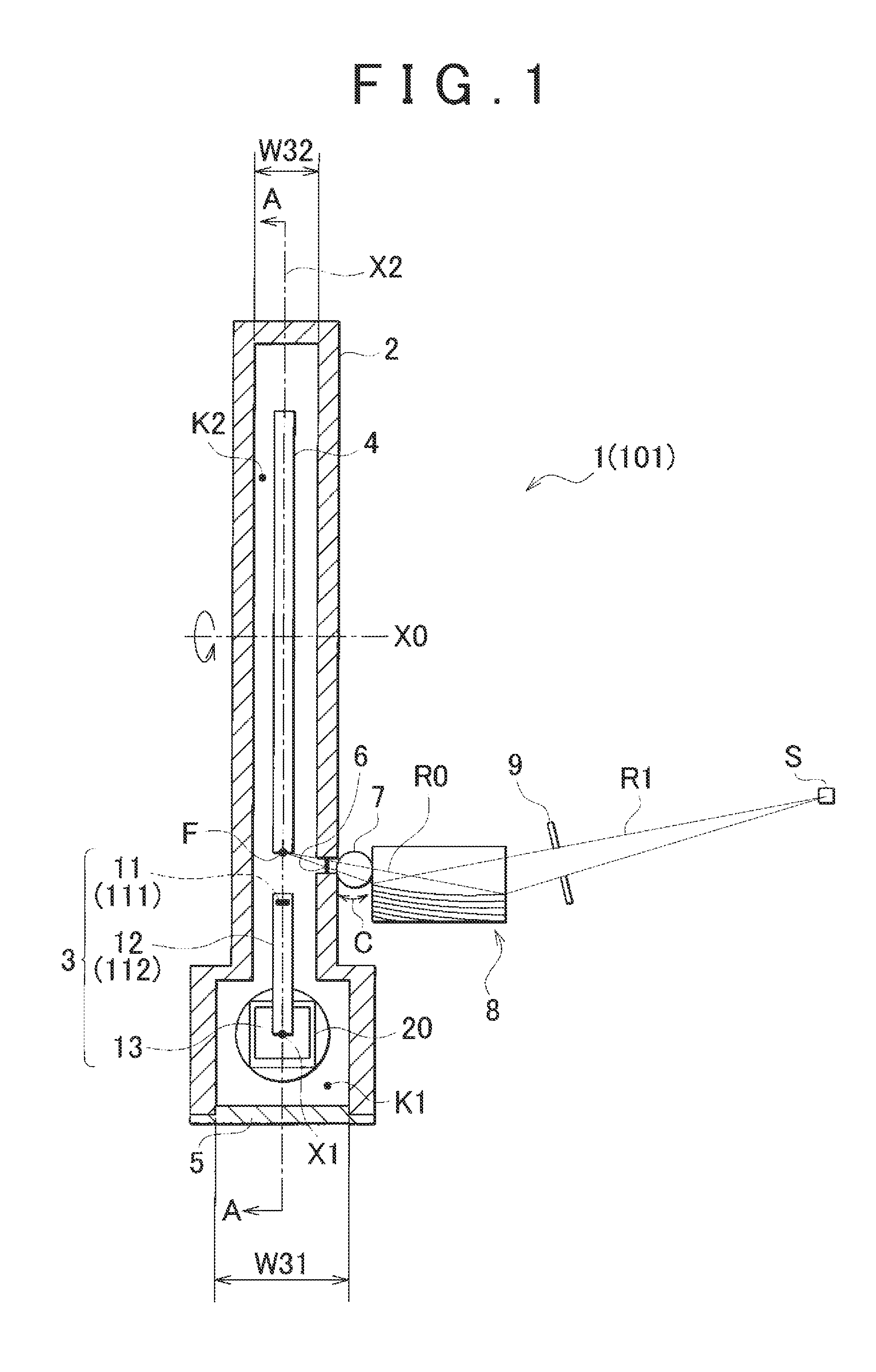
[0019]By reducing the width of the anticathode housing space of the casing in this manner, in a case in which an X-ray conditioning element (e.g., a monochromator, X-ray focusing mirror, or the like) is disposed outside the casing, it is possible to reduce the distance from a center line (i.e., the center line of the anticathode passing through the X-ray focal point) in the plane-parallel direction of the anticathode to the X-ray conditioning element. Reducing the distance from the X-ray focal point to the X-ray conditioning element makes it possible to increase the range of capture angles of X-rays emitted from the X-ray focal point that are captured by the X-ray conditioning element, and the range of capture lengths of X-rays that correspond to the capture angles, and the efficiency of X-ray focusing by the X-ray conditioning element can therefore be increased.
[0020]Furthermore, since the distance from the X-ray focal point to the X-ray conditioning element is reduced, attenuation of the intensity of X-rays due to air scattering can also be suppressed.
[0021]Preferably, in the X-ray generator according to the present invention, the width of the Wehnelt electrode is less than the width of the attachment part. The width of the attachment part of the electron gun can thereby be kept large despite the reduction in width of the Wehnelt electrode, and adverse effects on the workability of electron gun replacement can therefore be prevented.
[0022]The X-ray generator according to the present invention may further comprise an X-ray extraction window provided to the casing for housing the anticathode. The distance from a center line in the plane-parallel direction of the anticathode to the X-ray extraction window may be set so as to be less than the distance from the center line in the plane-parallel direction of the anticathode to an inside surface of a portion of the casing that houses the pedestal. Through this configuration, the distance between the X-ray conditioning element disposed outside the X-ray extraction window and the X-ray focal point on the anticathode can be reduced while ease of attachment and detachment of the electron gun with respect to the pedestal is ensured.
[0024]By reducing the width of the anticathode housing space of the casing in this manner, in a case in which an X-ray conditioning element (e.g., a monochromator, X-ray focusing mirror, or the like) is disposed outside the casing, it is possible to reduce the distance from a center line (i.e., the center line of the anticathode passing through the X-ray focal point) in the plane-parallel direction of the anticathode to the X-ray conditioning element. Reducing the distance from the X-ray focal point to the X-ray conditioning element makes it possible to increase the range of capture angles of X-rays emitted from the X-ray focal point that are captured by the X-ray conditioning element, and the range of capture lengths of X-rays that correspond to the capture angles, and the efficiency of X-ray focusing by the X-ray conditioning element can therefore be increased.

Problems solved by technology

A problem therefore arises in that a large portion of the X-rays generated from the X-ray focal point F cannot be effectively utilized.
In other words, a problem arises in that the efficiency of X-ray focusing by the X-ray conditioning element 59 cannot be maintained at a high level.
On the other hand, when the installation distance W4 of the X-ray conditioning element 59 is reduced, since specialized tools are needed to attach and detach the electron gun 52 inside the casing 57, maintenance must be performed by the manufacturer of the X-ray generator, which is extremely inconvenient.

Method used


Image

  • X-ray generator
  • X-ray generator
  • X-ray generator

Examples


first embodiment

[0035](First Embodiment of the X-ray Generator)

[0036]The X-ray generator of the present invention will be described based on embodiments. The present invention is, of course, not limited to these embodiments. The drawings are referred to in the following description, but constituent elements are sometimes shown at a scale other than the actual scale thereof in order to facilitate understanding of characteristic portions.

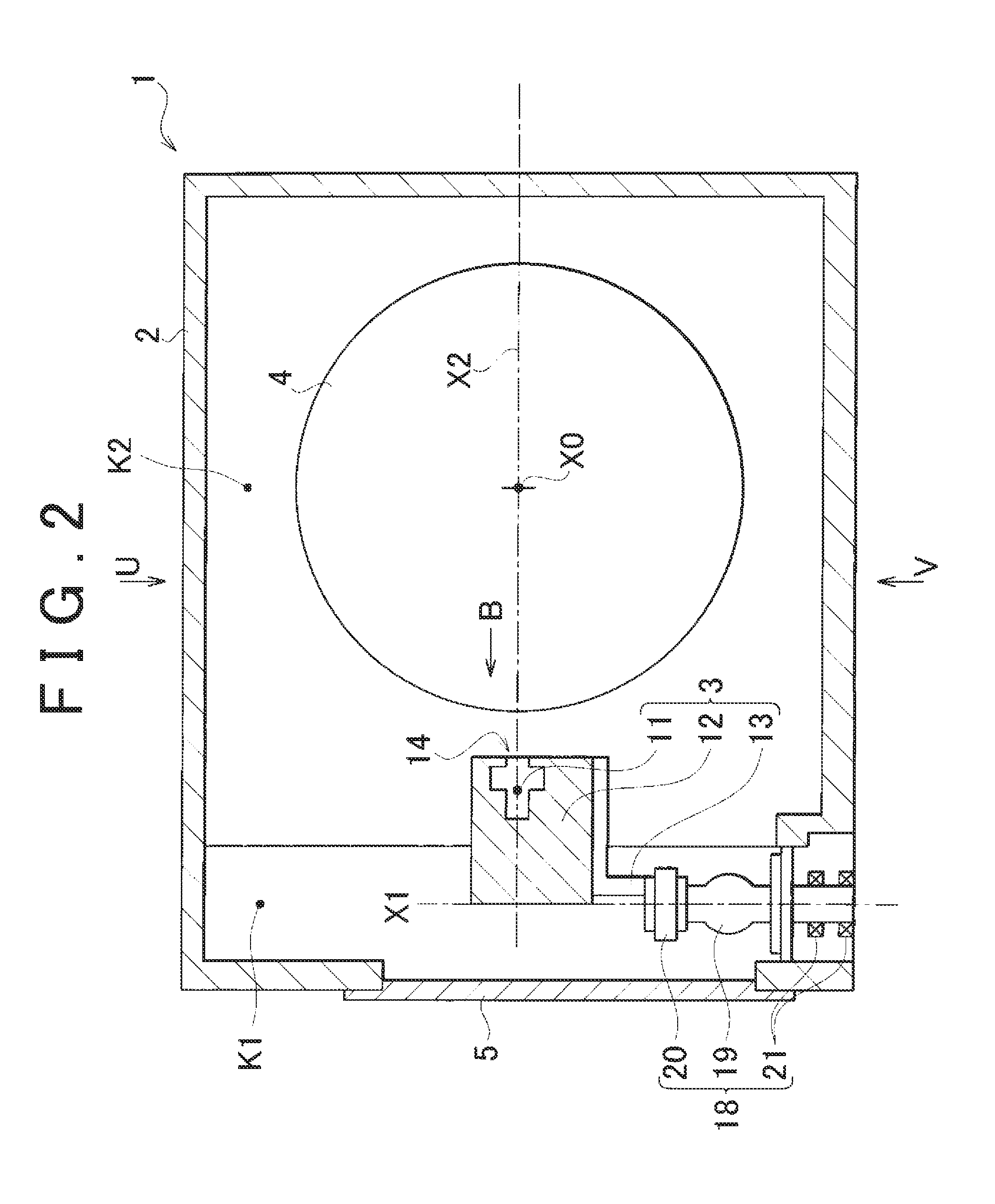
[0037]FIG. 1 is a sectional plan view showing an embodiment of the X-ray generator according to the present invention. FIG. 2 is a sectional side view showing the X-ray generator along line A-A of FIG. 1. FIG. 3 is an enlarged view showing the electron gun and the area surrounding the electron gun, which is a main part in FIG. 1.

[0038]In these drawings, an X-ray generator 1 has a metal casing 2, an electron gun 3 provided inside the casing 2, and a rotating anode 4 provided opposite the electron gun 3. An X-ray extraction window 6 is provided in a portion of a wall o...

second embodiment

[0079](Second Embodiment of the X-ray Generator)

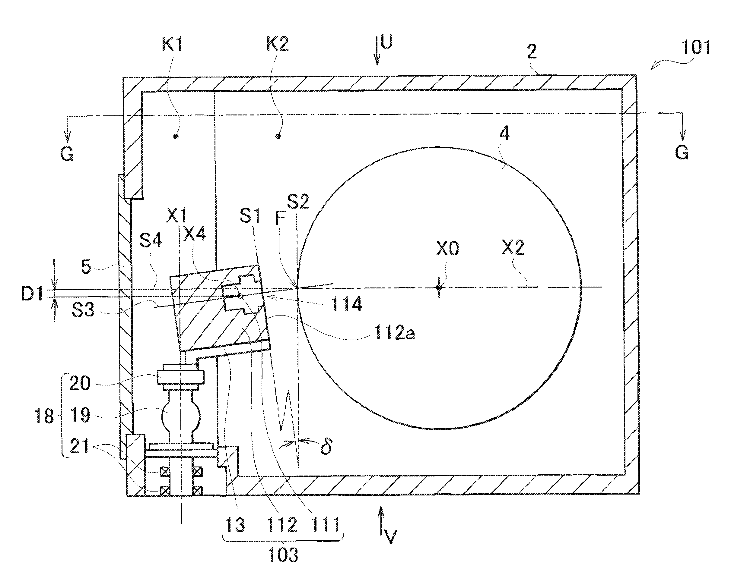
[0080]FIG. 8 shows another embodiment of the X-ray generator of the present invention. FIG. 8 is a sectional side view showing the X-ray generator. The sectional plan view along line G-G of this X-ray generator is the same as FIG. 1. Members in the present embodiment that are the same as in the embodiment shown in FIGS. 1 and 2 are indicated by the same reference symbols.

[0081]In the X-ray generator 101 of the present embodiment, an electron gun 103 has a Wehnelt electrode 112 formed of a conductive metal, and a filament 111 as a cathode is housed by a space formed inside the Wehnelt electrode 112. The filament 111 is formed of a coiled metal wire of length L1, as shown in FIG. 10. In FIG. 9, the filament 111 extends in the direction at a right angle to the paper surface (i.e., the direction through the paper surface). The Wehnelt electrode 112 is an electrode for controlling the progression direction of electrons by applying an electr...


PUM


Abstract

Provided is an X-ray generator for generating X-rays from an X-ray focal point that is a region in which electrons emitted from a filament impinge upon a rotating anode. The X-ray generator has a Wehnelt electrode for surrounding the filament, an attachment part formed integrally with the Wehnelt electrode, a pedestal to which the attachment part is attached, and a casing for housing the pedestal and the anticathode. The width of the space in which the anticathode is housed by the casing is less than the width of the space in which the pedestal is housed by the casing. The Wehnelt electrode extends into the space in which the anticathode is housed by the casing, in a state in which the attachment part is attached to the pedestal.

Description

BACKGROUND OF THE INVENTION[0001]1. Field of the Invention[0002]The present invention relates to an X-ray generator for generating X-rays from an anticathode by causing electrons generated from a cathode to impinge upon the anticathode.[0003]2. Description of the Related Art[0004]The above-mentioned X-ray generator is a device for generating X-rays which are irradiated to a sample to be analyzed in an X-ray diffraction device, for example. The device disclosed in Japanese Laid-open Patent Publication No. 2003-014895 (Patent Citation 1 ), is known as an example of this type of X-ray generator. As shown in FIG. 7, this X-ray generator has an electron gun 52 which houses a filament 51 as the cathode, and a rotating anode 53 which is provided opposite the filament 51. The electron gun 52 is formed in the shape of a flat rectangular solid, as shown in the partial magnified view of FIG. 7A. An electron gun in the shape of a flat rectangular solid is also disclosed in Japanese Laid-open Pa...

Claims


Application Information

Patent Timeline
Patent Type & Authority Patents(United States)
IPC IPC(8): H01J29/02H01J35/14H01J35/10H01J35/06H01J29/04H01J35/16
CPCH01J35/06H01J2235/166H01J2235/168H01J2235/086H01J2235/06H01J35/14H01J35/10H01J35/16H01J35/066H01J35/147
Inventor CHAKI, TOMOHIROKATO, KOICHINONOGUCHI, MASAHIROKAGEYAMA, MASASHIKURIBAYASHI, MASARU
Owner RIGAKU CORP
Learn More