
Focusing device based on inner coaxial shaft and focusing method based on inner coaxial shaft

A focusing device, coaxial technology, applied in welding equipment, laser welding equipment, metal processing equipment and other directions, can solve the problems of low processing efficiency and poor position consistency

Active Publication Date: 2019-03-29
WUHAN HGLASER ENG CO LTD
View PDF7 Cites 9 Cited by
  • Summary
  • Abstract
  • Description
  • Claims
  • Application Information

AI Technical Summary

Problems solved by technology

[0004] The point-to-point manual focus method is adopted, the processing efficiency is low, and the consistency of the focus position is poor

Method used


Image

  • Focusing device based on inner coaxial shaft and focusing method based on inner coaxial shaft
  • Focusing device based on inner coaxial shaft and focusing method based on inner coaxial shaft
  • Focusing device based on inner coaxial shaft and focusing method based on inner coaxial shaft

Examples


Embodiment 1

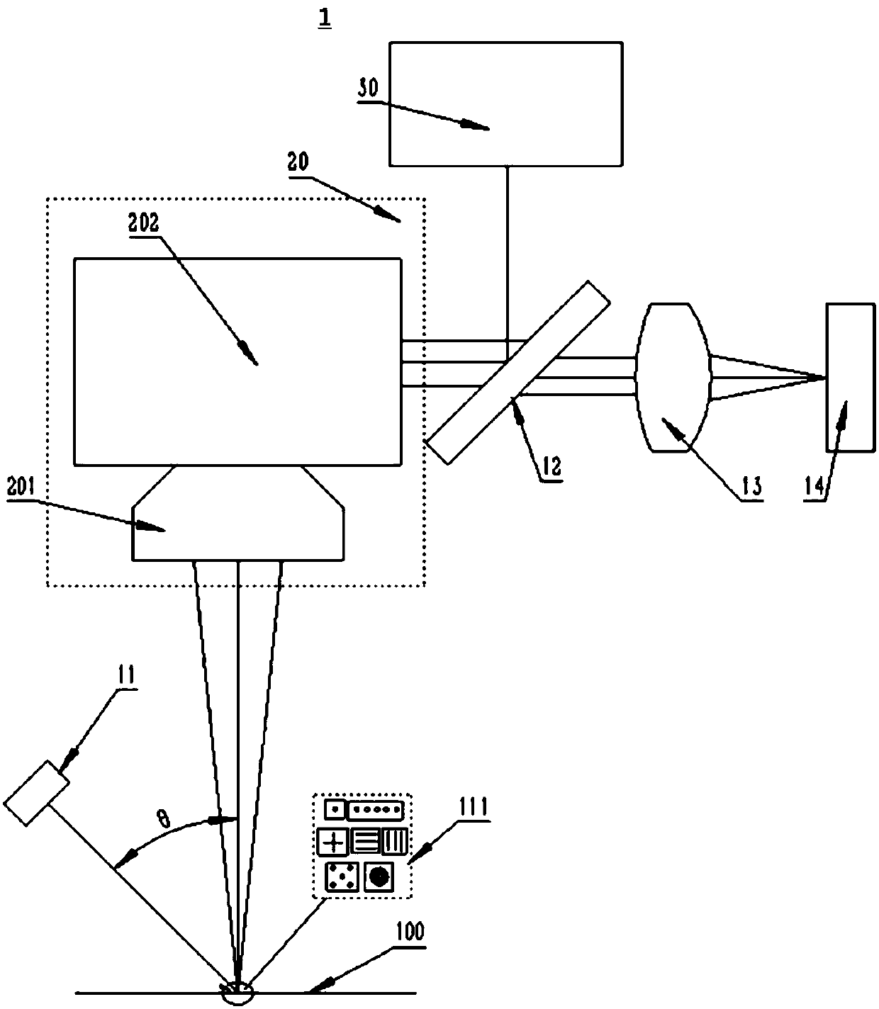
[0046] figure 1 A schematic structural diagram of an inner coaxial-based focusing device 1 provided by an embodiment of the present invention.

[0047] Please refer to figure 1 , the present embodiment provides a focusing device 1 based on an inner coaxial, the device includes a light source 11, a galvanometer focusing system 20, a beam splitter 12, a laser 30, a camera lens 13 and a sensor 14;

[0048] The light source 11 is set to output a light beam to the workpiece. The beam irradiates the surface of the workpiece to form a beam state 111. The image information of the beam state 111 is transmitted to the beam splitter 12 through the galvanometer focusing system 20, and the image information is transmitted to the camera through the beam splitter 12. lens 13 and sensor 14;

[0049] The camera lens 13 is configured to transmit the image information of the light beam to the sensor 14, and the sensor 14 receives the image information and obtains the position of the center of ...

Embodiment 2

[0066] This embodiment also provides a focusing method based on internal coaxial, using the above-mentioned focusing device 1 based on internal coaxial, the structure of focusing device 1 based on internal coaxial can refer to embodiment 1, the internal coaxial based The focusing method of the axis has all the functions of the focusing device 1 based on the inner coaxial.

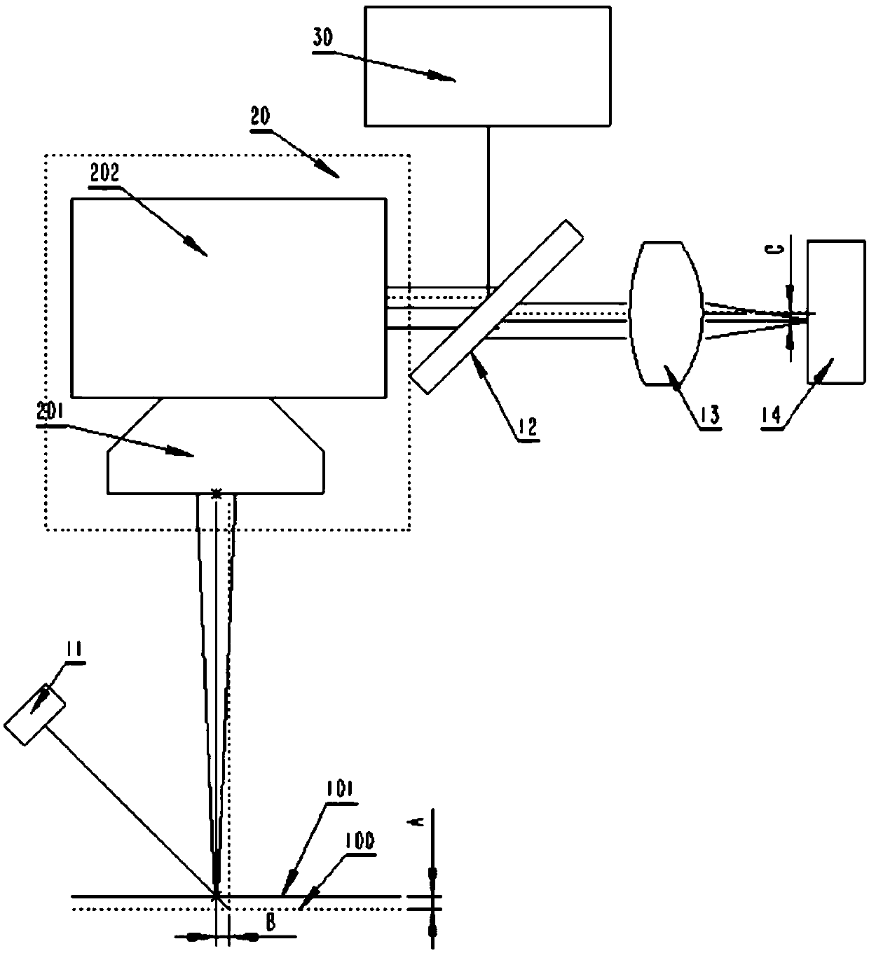
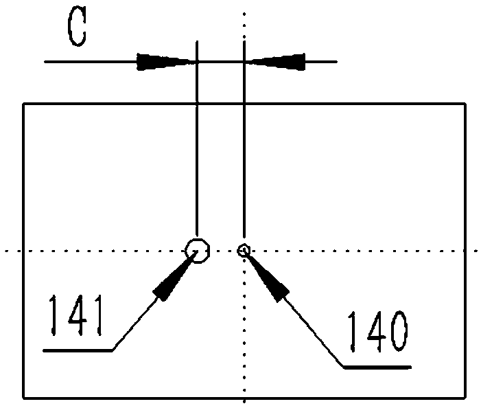
[0067] The method includes pre-adjusting the distance between the galvanometer focusing system 20 and the workpiece, finding the laser focal plane 100, turning on the light source 11 to output a beam of light that is at an angle θ with the main optical axis of the galvanometer focusing system 20 to the workpiece, and the image information of the beam passes through the field in sequence. mirror 201, vibrating mirror 202, and pass through the beam splitter 12, then arrive in the sensor 14 through the camera lens 13, and locate by software, the image position of the light beam on the sensor 14 is recorded as t...


PUM

PropertyMeasurementUnit
wavelengthaaaaaaaaaa
lengthaaaaaaaaaa

Abstract

The invention provides a focusing device based on an inner coaxial shaft and a focusing method based on the inner coaxial shaft, and belongs to the technical field of laser machining. The device comprises a light source, a galvanometer focusing system, a spectroscope, a laser device, a camera lens and a sensor, wherein the light source is used for outputting a light beam to a workpiece, the lightbeam is irradiated on the surface of the workpiece to form a light beam state, the image information of the light beam state is transmitted to the spectroscope through the galvanometer focusing system, and the image information is transmitted to the camera lens and the sensor sequentially through the spectroscope; the imaging lens is used for transmitting the image information to the sensor, the sensor receives the image information and processes and analyzes the image information by software to obtain a mass center position of the light beam; and the laser device is used for outputting laser,the laser is reflected to the galvanometer focusing system through the spectroscope, and the laser is focused to the workpiece through the galvanometer focusing system. According to the focusing device, the problems of low focusing efficiency and poor consistency can be solved, and the laser machining efficiency is improved; and the focusing method based on the inner coaxial shaft uses the devicementioned above.

Description

technical field [0001] The invention relates to the technical field of laser processing, in particular to an internal coaxial-based focusing device and an internal coaxial-based focusing method. Background technique [0002] Laser processing has been widely used in modern manufacturing, especially in the fields of precision processing and micro-processing, including cutting, marking, printing, drilling, engraving, scanning, etc. The requirements for flexibility, adaptability, intelligence and efficiency are getting higher and higher. The focus method in existing laser processing applications usually adopts manual visual inspection and physical detection method, but when facing workpieces with complex shapes, the point-to-point manual focus method is not only extremely inefficient but also poor in consistency, and the processing efficiency is difficult. Keep up with production requirements. [0003] The inventor found in the research that there are at least the following sh...

Claims


Application Information

Patent Timeline
Patent Type & Authority Applications(China)
IPC IPC(8): B23K26/046B23K26/04
CPCB23K26/04B23K26/046
Inventor 王雪辉王建刚雷桂明许维喻浩
Owner WUHAN HGLASER ENG CO LTD
Learn More