Battery charging case with changeable panel for an electronic device

a technology for electronic devices and charging cases, applied in the direction of substation equipment, instruments, transmission, etc., can solve the problems of bulky and bulky storage of several unused device cases, the phone case provider cannot point to any meaningful improvement or advantage over the case made by other manufacturers, and the cost of purchasing two, three or even more protective cases for any portable electronic device can be prohibitive for many, so as to achieve the effect of extra battery power

Active Publication Date: 2014-11-04
UNCOMMON
View PDF6 Cites 1 Cited by
  • Summary
  • Abstract
  • Description
  • Claims
  • Application Information

AI Technical Summary

Benefits of technology

The patent describes an improved protective case for electronic devices that solves the problems of previous cases. This case has a customizable design that allows for extra battery power and better aesthetics. It has a battery unit with charging ports and a main shell that attaches to the battery and protects the device. The case has openings for access to ports and control buttons and securely attaches to the device with a front and back edge. Overall, this case provides better protection and more battery power for electronic devices.

Problems solved by technology

However, other than some minor aesthetic differences, phone case providers have been unable to point to any meaningful improvements or advantages they provide over cases made by other manufacturers.
But purchasing two, three or even more protective cases for any portable electronic device is cost prohibitive for many.
Also, even where cost may not be an issue, the bulkiness of having several unused device cases can be a problem.
The solution to these problems has been missed by prior case designers and manufacturers.
Despite even the best efforts to keep a device's battery charged, many users run into the problem of a low battery.
In some devices (e.g., Apple's iPhone line), carrying spare batteries is not an option, as the battery is sealed within the device.
However, providing security in this area has never been a focus of protective cases.

Method used


Image

  • Battery charging case with changeable panel for an electronic device
  • Battery charging case with changeable panel for an electronic device
  • Battery charging case with changeable panel for an electronic device

Examples


Embodiment Construction

[0039]While this invention is susceptible of embodiments in many different forms, there is shown in the drawings and will herein be described in detail at least one preferred embodiment of the invention with the understanding that the present disclosure is to be considered as an exemplification of the principles of the invention and is not intended to limit the broad aspect of the invention to any of the specific embodiments illustrated.

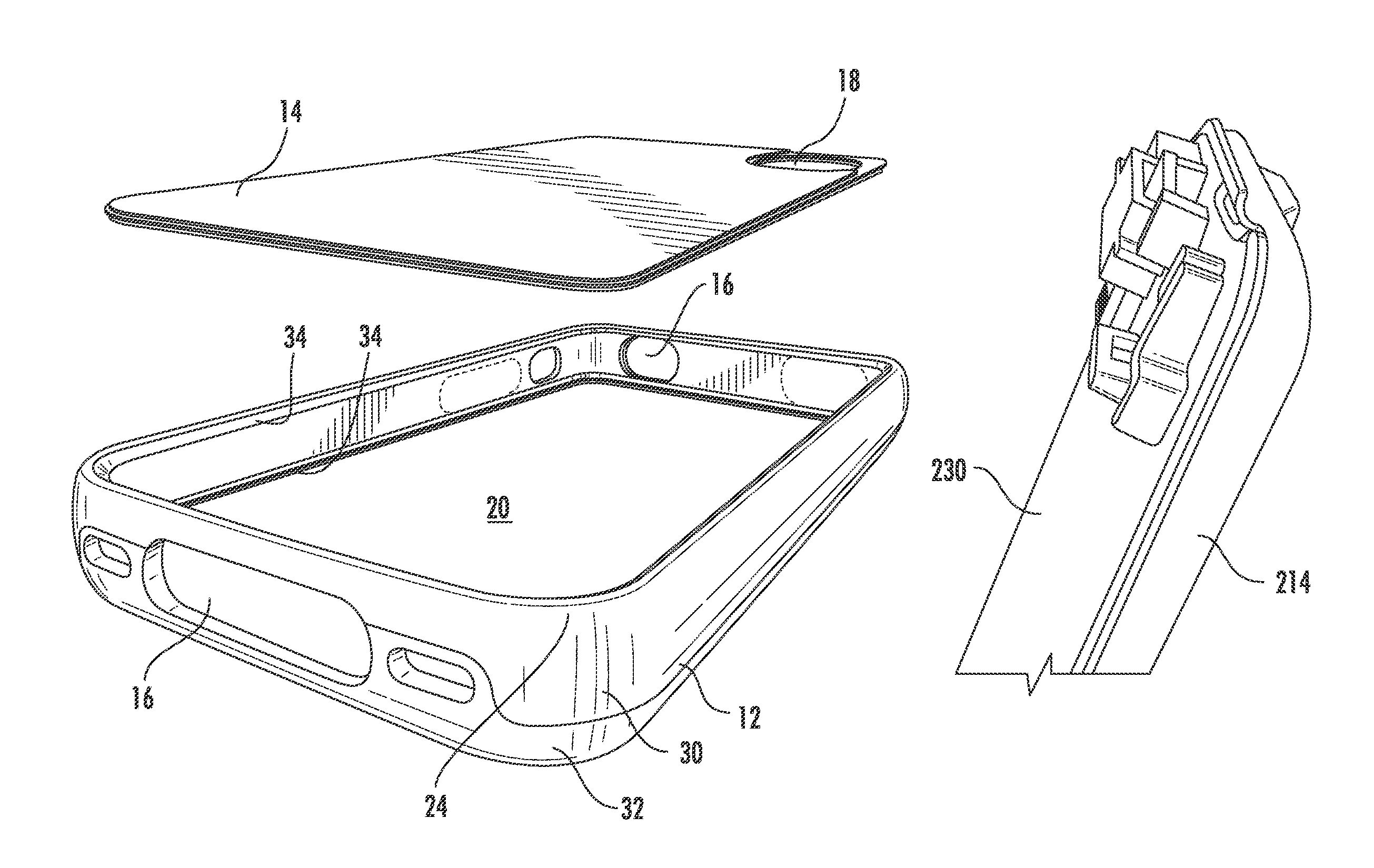
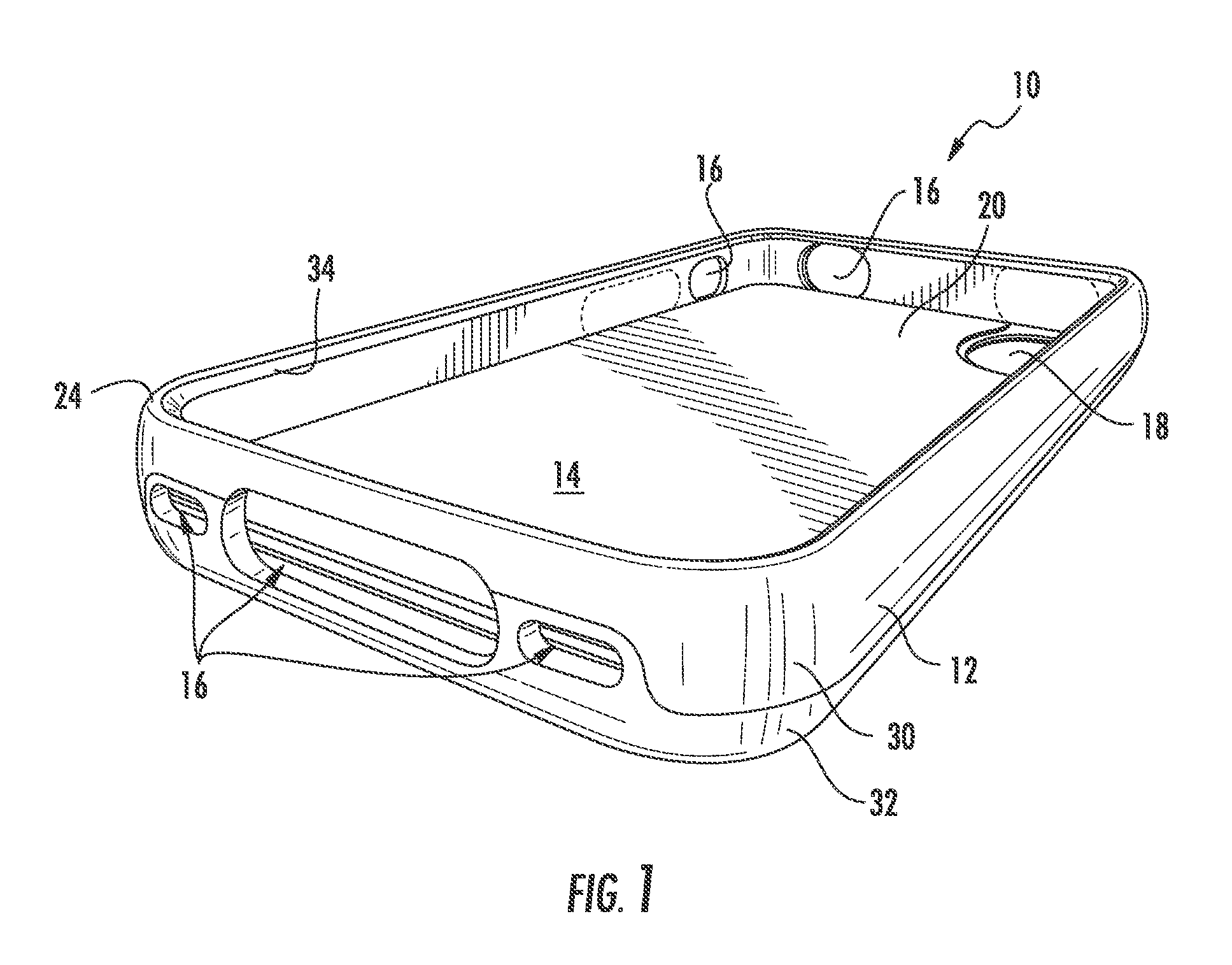
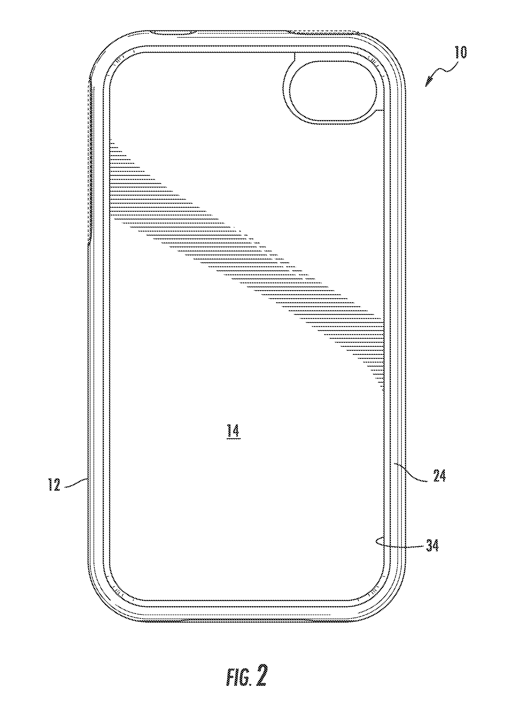
[0040]Referring to FIGS. 1-15, there are illustrated embodiments of a protective case, generally designated by the numerals 10 and 110. The particular illustrated cases 10 (FIGS. 1-7 and 15) and 110 (FIGS. 8-14) are for an Apple® iPhone 4 / 4S and an iPhone 5, respectively. In fact, while all the embodiments illustrated are directed to iPhones, it should be understood that the principles of the invention can be more broadly applied to most any smart phone, as well as other types of portable electronic devices such as gaming consoles (e.g., Gameboy), ta...


PUM


Abstract

A charging case or system for an electronic device case, having a protective housing capable of aesthetic alteration, includes a replaceable and customizable shell and a rechargeable battery unit. A plurality of shells may have different images thereon and can be interchanged in a continuous sidewall portion to alter the look of the case. The shell images may include various colors, pictures, designs, logos, or even text.

Description

RELATED APPLICATIONS[0001]This application is a continuation-in-part of U.S. application Ser. No. 13 / 660,147, titled “Electronic Device Case With Changeable Panel” filed on Oct. 25, 2012, which is a continuation-in-part of U.S. patent Design application Ser. No. 29 / 431,945, filed on Sep. 12, 2012, which is a continuation-in-part of U.S. patent Design application Ser. No. 29 / 417,069, filed on Mar. 29, 2012. Each of the priority documents is hereby incorporated by reference.TECHNICAL FIELD OF THE INVENTION[0002]The present invention relates to charging and protection devices and / or systems for electronic devices such as, for example, a smart phone, a gaming device, a tablet or the like. Specifically, the invention relates to customizable devices for providing extra charging power and protection for an electronic device.BACKGROUND OF THE INVENTION[0003]Mobile phone cases have very quickly blossomed into a multi-billion dollar industry. With each new entry into the field, phone cases be...

Claims


Application Information

Patent Timeline
Patent Type & Authority Patents(United States)
IPC IPC(8): H04M1/04G06F1/16H04M1/02H04B1/38H04M1/00
CPCH04M1/0283G06F1/1635H04M1/04H04B1/3888H02J7/0044H02J7/342
Inventor HONG, JOHN
Owner UNCOMMON
Why Eureka
Try Eureka