Image forming apparatus which uses electrostatic latent image for color misregistration correction
an image forming apparatus and color misregistration technology, applied in the field of electrophotography, can solve the problems of color misregistration (positional shift), color misregistration, impede synchronization, etc., and achieve the effect of suppressing toner consumption and preventing usability from lowering
- Summary
- Abstract
- Description
- Claims
- Application Information
AI Technical Summary
Benefits of technology
Problems solved by technology
Method used
Image
Examples
first embodiment
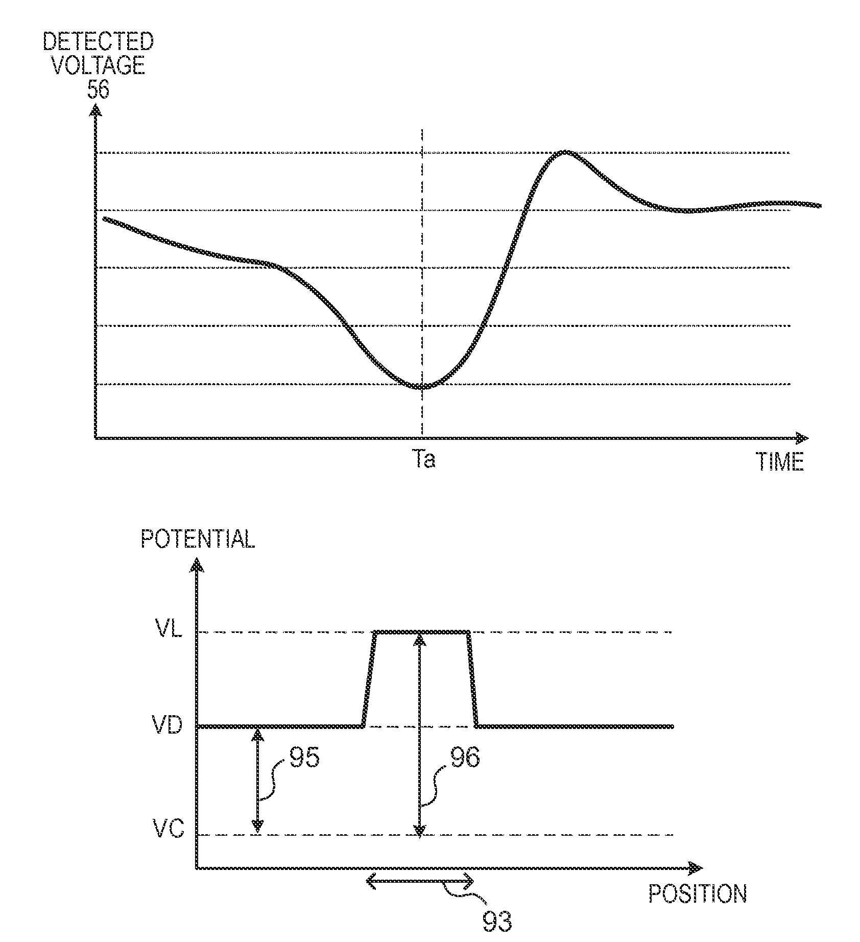
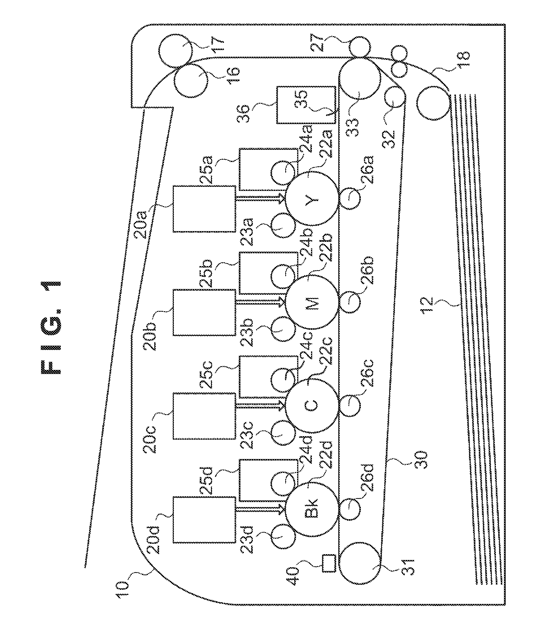
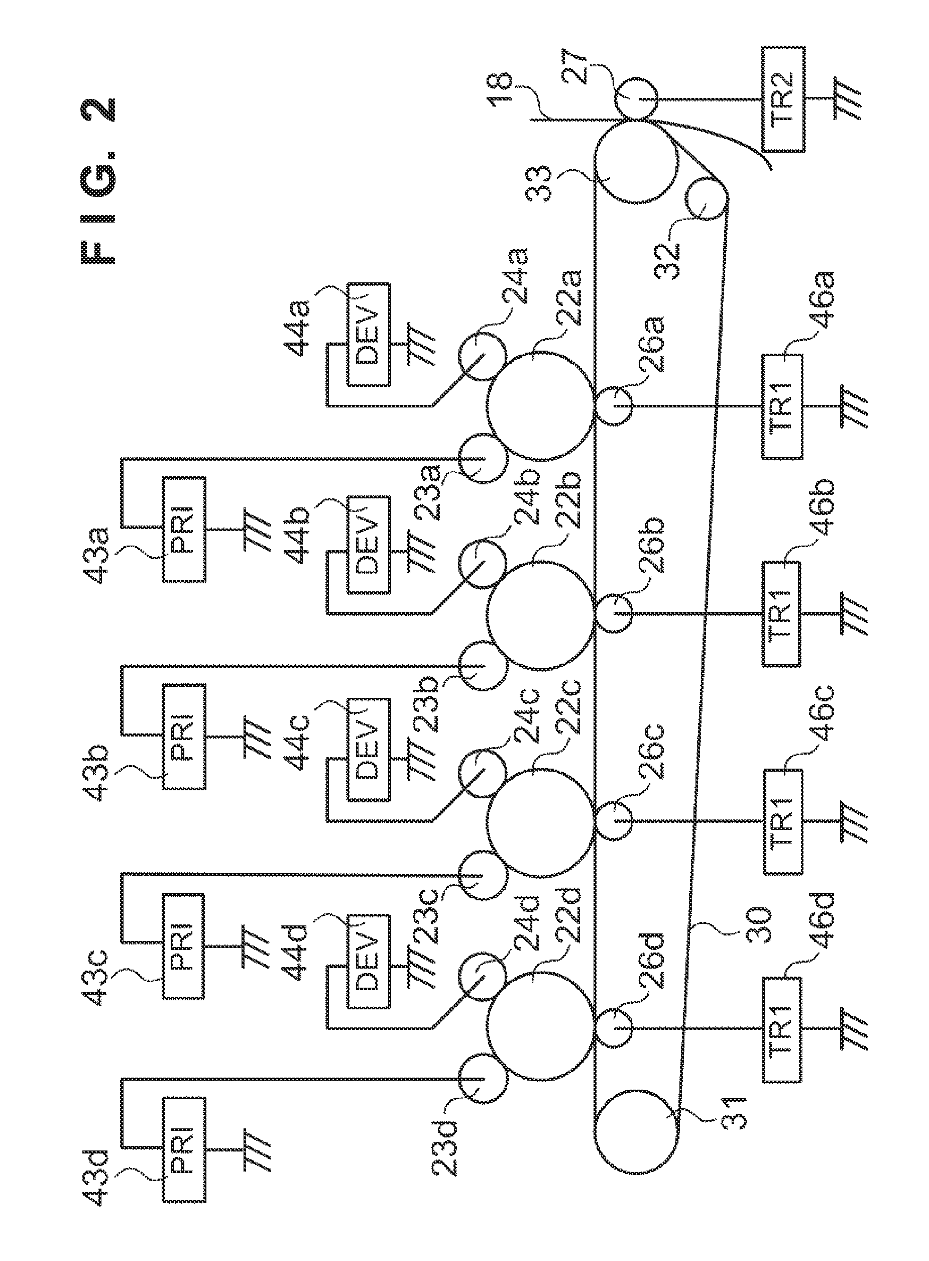
[0027]FIG. 1 is a view showing the arrangement of an image forming unit 10 of an image forming apparatus according to the present embodiment. Note that the lower-case alphabetic characters a, b, c, and d added to reference numerals as suffixes indicate that the members of interest correspond to yellow (Y), magenta (M), cyan (C), and black (Bk). Reference numerals without the suffixes a, b, c, and d in the lower-case alphabetic characters are used when the colors need not be discriminated. A photosensitive member 22 is an image carrier and is rotatably driven. A charging roller 23 charges the surface of the corresponding photosensitive member 22 to a uniform potential. For example, the charging bias output from the charging roller 23 is −1200 V, and the surface of the photosensitive member 22 is charged by this to a potential (dark potential) of −700 V. A scanner unit 20 scans the surface of the photosensitive member 22 by a laser beam corresponding to the image data of an image to b...
second embodiment
[0073]In the second embodiment, points of difference from the first embodiment will mainly be described next. In the first embodiment, the current flowing via the charging high-voltage power supply circuit 43 and the charging roller 23 is detected to detect the latent image marks 80. In the second embodiment, latent image marks 80 are detected by a current that flows via a primary transfer high-voltage power supply circuit 46 and a primary transfer roller 26. FIG. 13 shows an arrangement for detecting the latent image marks 80 according to the present embodiment. The arrangement shown in FIG. 13 is different from that shown in FIG. 3 in that diodes 1601 and 1602 are directed in opposite directions. This is because an output terminal 53 should output a transfer bias of, for example, +1000 V.
[0074]In a current detection circuit 47 according to the present embodiment, a high-pass filter is formed from a resistor 100 and a coil 89 that is an inductive element. However, the high-pass fil...
third embodiment
[0077]In the third embodiment, points of difference from the first embodiment will mainly be described next. In the first embodiment, the current flowing via the charging high-voltage power supply circuit 43 and the charging roller 23 is detected to detect the latent image marks 80. In the third embodiment, latent image marks 80 are detected by a current that flows via a developing high-voltage power supply circuit 44 and a developing sleeve 24. FIG. 14 shows an arrangement for detecting the latent image marks 80 according to the present embodiment. The arrangement shown in FIG. 14 is different from that shown in FIG. 3 in that the output of an operational amplifier 70 is directly input to an engine control unit 54, and the engine control unit 54 is provided with a digital filter 325 and a comparison unit 326. Note that an output terminal 53 applies a developing bias of, for example, −400 V.
[0078]In the present embodiment, a detected voltage 56 input from the operational amplifier 7...
PUM
 Abstract
Description
Claims
Application Information
 - R&D
- Intellectual Property
- Life Sciences
- Materials
- Tech Scout
- Unparalleled Data Quality
- Higher Quality Content
- 60% Fewer Hallucinations
Browse by: Latest US Patents, China's latest patents, Technical Efficacy Thesaurus, Application Domain, Technology Topic, Popular Technical Reports.
© 2025 PatSnap. All rights reserved.Legal|Privacy policy|Modern Slavery Act Transparency Statement|Sitemap|About US| Contact US: help@patsnap.com


