Mounting device and method of installing of a solar panel

a technology of solar panels and mounting devices, which is applied in the direction of photovoltaics, heat collector mounting/support, sustainable buildings, etc., can solve the problems of many bolts and hence many holes, and the cost of such arrangements is considerable, and achieves the effect of convenient installation of mounting

Inactive Publication Date: 2014-11-11
CEL F SOLAR SYST
View PDF24 Cites 6 Cited by
  • Summary
  • Abstract
  • Description
  • Claims
  • Application Information

AI Technical Summary

Benefits of technology

[0010]In an aspect there is provided a solar panel mounting anchor adapted for mounting a solar panel on a flat roof, the anchor comprising integral ballast, and edges comprising a resilient material and at least one engagement feature adapted to receive a solar panel and to space the panel from said roof, and a base adapted to inhibit slipping of the anchor on said roof. In one possibility the integral ballast is such that the mass of the anchor is at least 15 kg. These and other examples of the invention have the advantage of providing a secure and easily installable mounting for a flat roof which is able to adapt to irregularities in roof shape and in which the hazard associated with mounting a solar panel to a roof is substantially reduced because, if the ballast is accidentally dropped during installation it is less likely to be damaged or to cause damage or injury. Further advantageously the resilient nature of the anchor / ballast structure enables it to deform to absorb stresses associated with any possible misalignment of the ballast and support structure with a solar panel which is assembled to the structure.

Problems solved by technology

Particularly in the case of photovoltaic cells, the cost of such arrangements is considerable.
The size and arrangement of solar panel structures makes them susceptible to damage by winds and it is necessary to secure the panels to prevent them from being damaged or blown away in high winds.
As such, many bolts and hence many holes may be required.
This presents a problem, particularly for a flat roof, in that each of the holes must be individually sealed to prevent water seeping through the holes in the roof and damaging the building.
However hoisting large blocks of concrete onto a roof and manoeuvring them can present a substantial hazard and / or risk damaging the structure of the roof.

Method used


Image

  • Mounting device and method of installing of a solar panel
  • Mounting device and method of installing of a solar panel
  • Mounting device and method of installing of a solar panel

Examples


Embodiment Construction

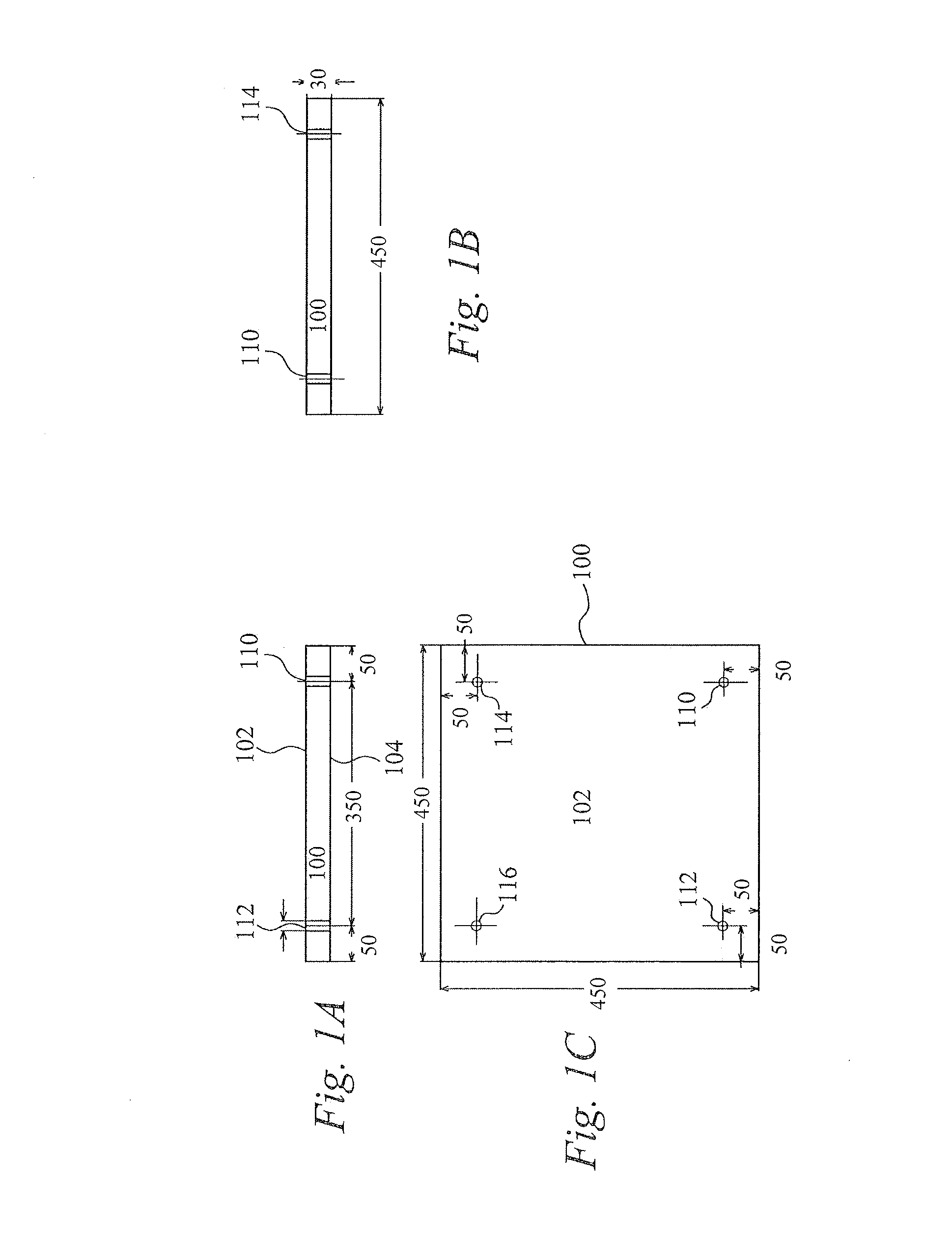
[0080]FIG. 1 shows a resilient edged ballast 100 and, in FIG. 1: FIG. 1A shows a side view, FIG. 1B shows an end view and FIG. 1C shows a top down view of a block 100. Block 100 has first and second major surfaces 102, 104. Holes 110, 112, 114, 116 are laterally offset from the ends and sides of the block substantially adjacent the corners and pass through the block 100 from the first major surface 102 to the second major surface 104. In the example of FIG. 1 the first and second major surfaces 102, 104 of the block 100 are substantially square in shape and 450 mm by 450 mm in size. The holes 110, 112, 114, 116 are each similarly spaced from the two respective nearest sides of the block 100 by 50 mm. The block 100 is 30 mm thick. As will be appreciated by the skilled practitioner in the context of the present disclosure, the stated dimensions are merely a particularly advantageous example and other sizes of block are contemplated.

[0081]FIG. 2 shows a base 120 for block 100 and, in F...


PUM


Abstract

A solar panel mounting anchor adapted for mounting a solar panel on a flat roof, the anchor comprising integral ballast, and edges comprising a resilient material and at least one engagement feature adapted to receive a solar panel and to space the panel from said roof, and a base adapted to inhibit slipping of the anchor on said roof. Preferably the integral ballast is such that the mass of the anchor is at least 15 kg.

Description

CROSS-REFERENCE TO RELATED APPLICATIONS[0001]This application is a continuation-in-part of International Application No. PCT / GB2011 / 051685, filed Sep. 8, 2011 (and published as WO 2012 / 032352); which claims priority to UK Patent Application No. 1015019.1, filed Sep. 9, 2010; both of which are incorporated by reference in their entireties.BACKGROUND OF THE INVENTION[0002]The present invention relates to a mounting device for a structure such as a solar panel and to a method of installing a solar panel.[0003]The problems of anthropogenic climate change are well known. Micro-power generation, for example using solar panels, is an increasingly popular way to provide a renewable source of energy for domestic and commercial use.[0004]Solar panels incorporating photovoltaic cells or heat collectors (such as flat plate collectors used for heating water) are typically large planar structures manufactured from relatively rigid, relatively lightweight materials. In use these structures must be...

Claims


Application Information

Patent Timeline
Patent Type & Authority Patents(United States)
IPC IPC(8): F24J2/46H01L31/042F24J2/52H01L31/048E04D13/18
CPCF24J2002/5292F24J2002/4658F24J2/5237F24J2/526Y02B10/12F24J2/5245Y02B10/20H01L31/0424Y02E10/50F24J2/5252H01L31/0422F24J2002/5284Y02E10/47H01L31/0484H02S20/00H02S20/24H02S30/10F24S25/11F24S25/60F24S25/617F24S25/63F24S25/65F24S2025/016F24S2025/02Y02B10/10F24S25/00H01L31/042H01L31/048H02S20/25F24S25/61
Inventor KNAPP, KEVIN
Owner CEL F SOLAR SYST
Why Eureka
Try Eureka