Cutting insert carrier

a cutting insert and carrier technology, applied in metal-working equipment, metal-working equipment, milling equipment, etc., can solve the problem of time-consuming and labor-intensive problems in the case of cutting inserts such as tools

Inactive Publication Date: 2014-11-11
KENNAMETAL INC
View PDF7 Cites 0 Cited by
  • Summary
  • Abstract
  • Description
  • Claims
  • Application Information

AI Technical Summary

Benefits of technology

[0007]Proceeding from this, the invention is based on the object of specifying a cutting insert carrier wherein exchanging the cutting inserts is simplified.
[0009]In comparison with the previous cutting insert carriers / blade heads, this concept of the common setting element for all clamping elements therefore significantly reduces and simplifies the amount of fitting required and, consequently, the setup time, i.e. the time required to prepare the tool for use. It is no longer necessary for each separate insert seat to be fastened individually.
[0012]The clamping elements in this case are preferably realized as a clamping lever having a first lever arm that acts upon the respective cutting insert. Preferably, in this case, the clamping lever is rotatably mounted on the tool basic body. An actuation by means of the setting element therefore results in a movement, in particular a rotational movement. Appropriate design of the clamping lever makes it possible to achieve sufficiently high clamping forces / locking forces to ensure that the cutting inserts are reliably fastened in the insert seat.
[0026]In a preferred design, however, the adjusting elements are realized, in particular, as adjusting screws, which are supported on a counter-bearing surface of the setting element. In the case of this design, the setting element is at the same time fixed and held in the respective position by means of the adjusting screw. An additional actuation of the fastening elements is therefore not required, and is also not provided. This enables the setting element to be adjusted in a particularly simple and, at the same time, highly precise manner through actuation of the setting screw. Preferably, at least two setting screws are provided, which are realized and disposed for adjustment of the setting element in opposing directions, i.e. the one setting screw is provided for releasing the clamping elements and the other setting screw is provided for tightening the clamping elements. As an alternative to this, it is possible, in principle, for these functions to be integrated also into one setting screw, which then is a double-action setting screw.
[0031]This is particularly simple in the case of tools having the indexable inserts disposed on a front face. Thus, in the case of front face milling cutters, the cutting inserts are aligned approximately perpendicularly in relation to the machining plane, i.e. their base sides or flat sides are aligned at least approximately perpendicularly in relation to the front, and therefore in relation to the machining plane of the face milling cutter. For the purpose of clamping, the clamping elements are applied to a flat side of the indexable cutting insert, and therefore, in the case of such face milling cutters, exert a force in the circumferential direction. Overall, this enables the individual indexable inserts to fall (downward) out of the insert seats, toward the front face, and to be caught by the pockets.

Problems solved by technology

Owing to the large number of cutting inserts, exchanging the cutting inserts in the case of such a tool is usually very time-consuming, since each cutting insert has to be fastened individually into the respective insert seat by means of a respective clamping element, for example by means of a clamping claw or clamping screw.

Method used


Image

  • Cutting insert carrier
  • Cutting insert carrier
  • Cutting insert carrier

Examples


Embodiment Construction

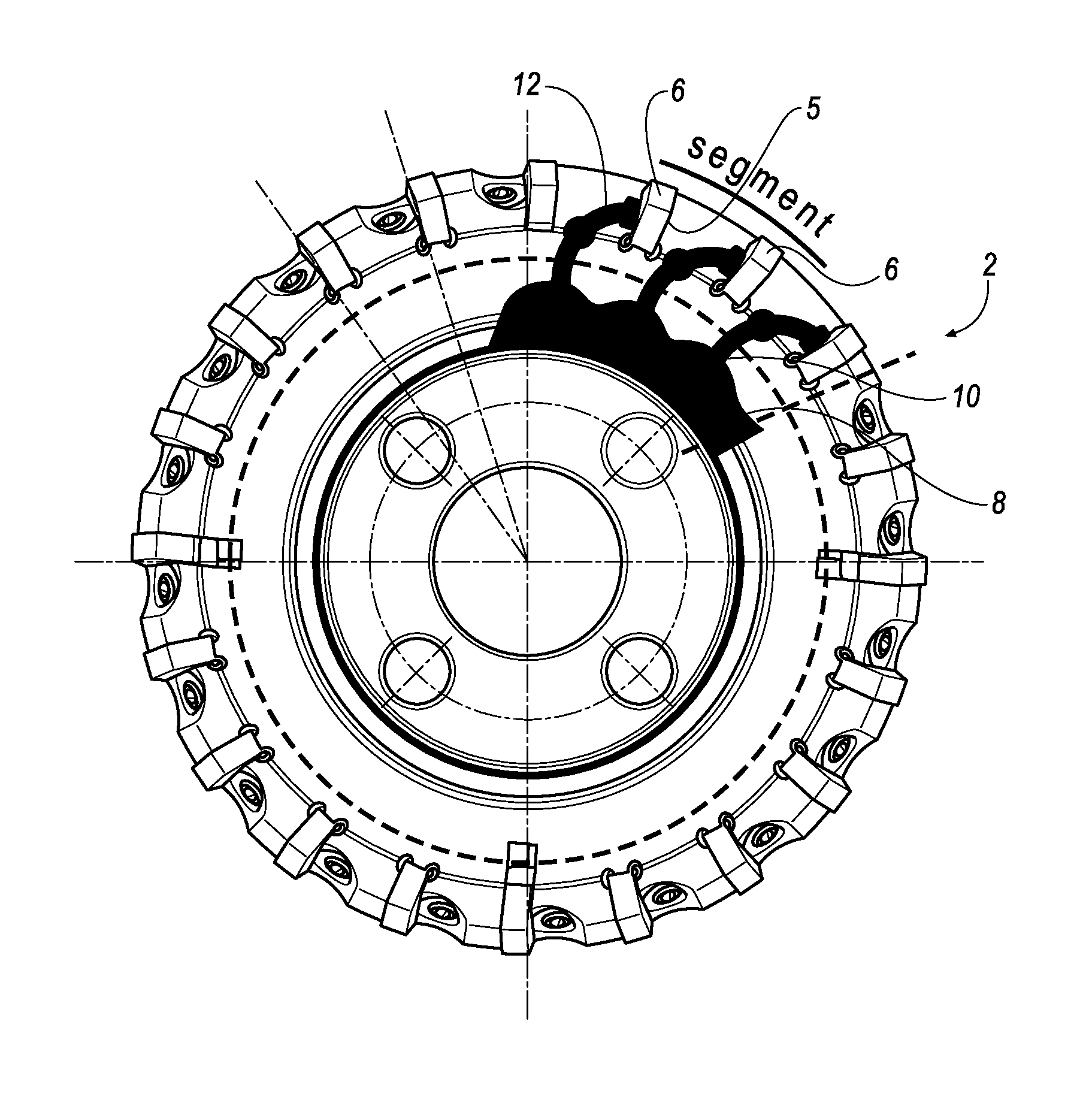
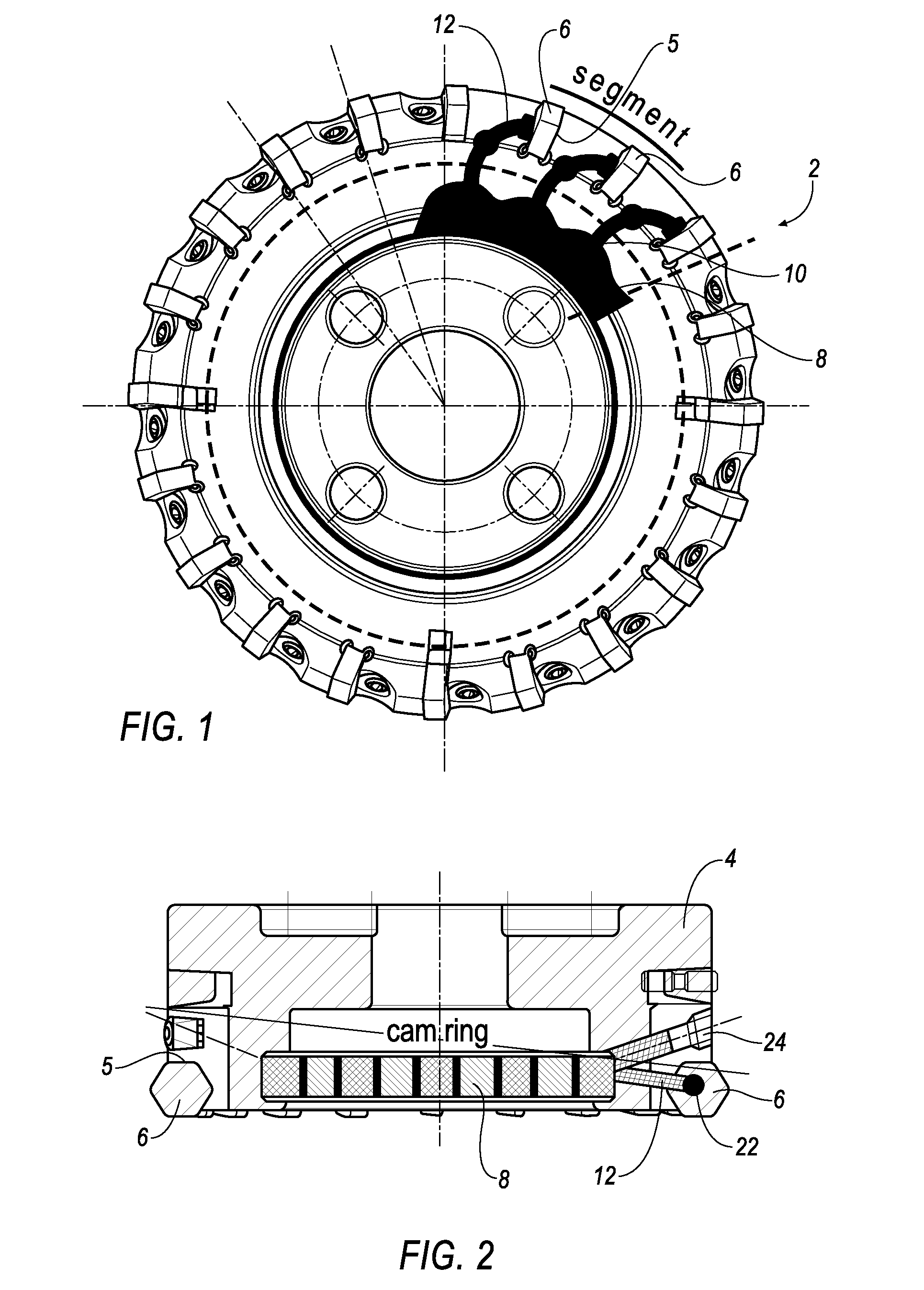
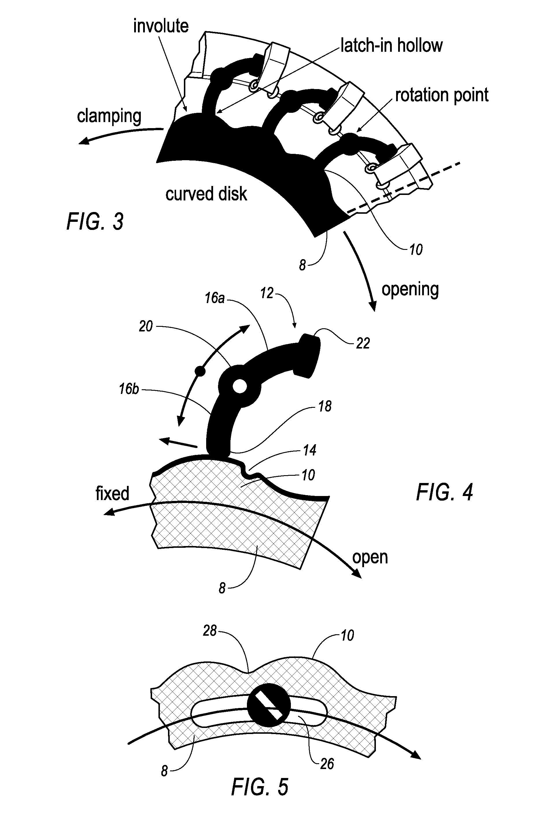
[0042]Represented in the exemplary embodiment, as a blade head, is a front face milling cutter (2), which has a cutting insert carrier, defined by a tool basic body (4), and which has a multiplicity of cutting inserts (6) that are realized, in particular, as indexable cutting inserts and that are each disposed in an insert seat (5) of the cutting insert carrier (4). As can be seen, in particular, from comparison of the representations according to FIG. 1 and FIG. 2, the cutting inserts (6) in this case are disposed around the circumference on the front face of the tool basic body. Provided on the front face is a setting element, realized as a curved disk (8), which is disposed so as to be rotatable relative to the tool basic body (4). On its circumferential side, the curved ring (8) has a multiplicity of cams (10), which constitute a path guide for a constrained guidance for clamping elements (12) realized as clamping levers. As shown, in particular, by FIG. 4, the cams (10) have a ...


PUM


Abstract

The cutting insert carrier, in particular for a face milling cutter (2) comprises a tool basic body (4), having a multiplicity of insert seats (5), in which cutting inserts (6) are received. Rotatably fastened to the tool basic body (4) is a setting element, which is realized, in particular, as a curved ring (8) and which has circumferential cams (10), by means of which the clamping levers (12) are actuated for the purpose of fastening the cutting inserts (6) in a locking manner. The setting element (8) enables all clamping levers (12) to be actuated jointly, at the same time, such that all cutting inserts (6) are simultaneously released or locked in their insert seats (5). As a result, the assembly and setup time for insert changing is reduced significantly in comparison with conventional systems.

Description

CLAIM TO PRIORITY[0001]This application is a National entry application of German Application No. 102011016921.0, filed Apr. 13, 2011, the entire contents of which is incorporated herein by reference.BACKGROUND OF THE INVENTION[0002]1. Field of the Invention[0003]The invention relates to a cutting insert carrier, also termed a blade head, in particular for a face milling cutter, comprising a tool basic body, which has a plurality of insert seats, in particular distributed around the circumference thereof, for receiving cutting inserts for workpiece machining.[0004]2. Description of Related Art[0005]It is necessary for the cutting insert carrier to be regularly fitted with the cutting inserts, in particular indexable cutting inserts, which become worn during workpiece machining and which therefore must be exchanged. The individual indexable cutting inserts in this case must be aligned in a defined position in their insert seats, such that the cutting edges of the individual cutting i...

Claims


Application Information

Patent Timeline
Patent Type & Authority Patents(United States)
IPC IPC(8): B23C5/22B23C5/06
CPCB23C5/2243B23C5/06B23C5/2295B23C2260/12Y10T407/192Y10T407/191
Inventor HOBOHM, UWE
Owner KENNAMETAL INC
Why Eureka
Try Eureka