
RFID memory devices

a memory device and rfid technology, applied in the direction of information storage, subscriber station connection selection arrangement, indirect connection, etc., can solve the problems of mechanical resonance of a vibrating member being typically damped and loss manifesting

Active Publication Date: 2014-11-11
BLUECHIIP LTD
View PDF11 Cites 7 Cited by
  • Summary
  • Abstract
  • Description
  • Claims
  • Application Information

AI Technical Summary

Benefits of technology

The invention is about maximizing the change in impedance caused by resonance of two parts in a system. The goal is to make this resonance occur at different magnetic field directions, so that the resulting change in impedance is maximized. This can be useful in creating systems that can resonate at different directions and frequencies, for example in magnetic resonance imaging (MRI).

Problems solved by technology

In addition, mechanical resonances of a vibrating member are typically damped by a number of mechanisms including intrinsic causes such as visco-elastic and thermo-elastic loss.
Such losses also manifest in the equivalent electrical circuit as resistive elements.

Method used


Image

  • RFID memory devices
  • RFID memory devices
  • RFID memory devices

Examples


Embodiment Construction

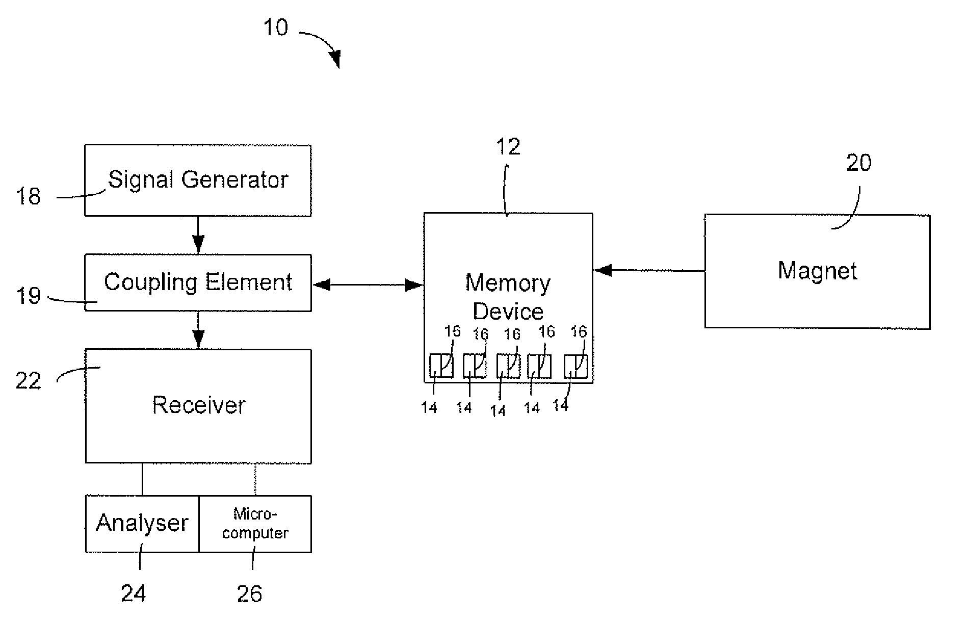
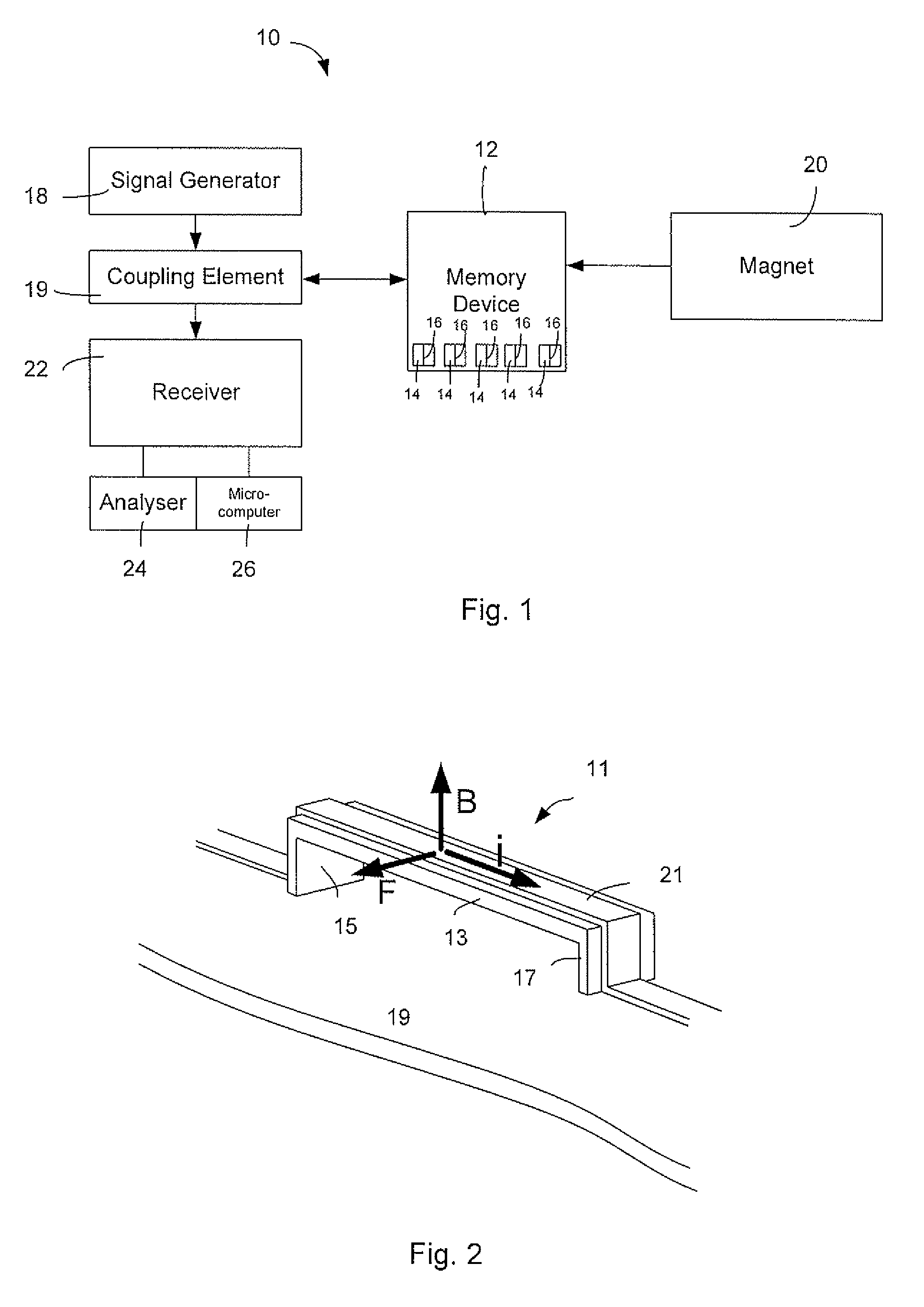
[0096]Referring to FIG. 1, a data reading system 10 includes a memory device 12 that may be attached to an item to provide information about the item. The memory device 12 includes a plurality of resonant members 14 of a bridge-type structure having different resonant frequencies, and conductor portions 16 extending along the length of the resonant members 14. Bridge-type structure resonant members are, for example, beams that are attached / held against movement at both ends. The presence or absence of a resonant member 14 at a particular resonant frequency represents a binary digit.

[0097]The data reading system 10 also includes a signal generator 18 that includes a coupling element 19 for electrodynamically coupling the signal generator to the memory device 12 in order to apply an excitation signal to the memory device 12. and the system 10 also includes a magnetic field generator 20 for applying a magnetic field across the resonant members 14. The magnetic field generator 20 may in...


PUM


Abstract

An RFID memory device includes two arrays of resonant members. A first array extends in a first member direction and a second array extends in a second member direction. The device includes one or more elements for transforming energy associated with vibration of the resonant members into a change in impedance of an electrical equivalent circuit of the memory device. The magnitude of impedance change caused by resonance of the first resonant members is maximized at a different magnetic field direction to that at which the magnitude of the impedance change caused by resonance of the second resonant members is maximized. Thus, different data may be encoded on each array and separately read. The resonant members may form part of a common electrical conductor that forms a coupling element for coupling with an applied excitation signal and causing vibration of the resonant members.

Description

TECHNICAL FIELD[0001]The present invention relates to RFID memory devices, interrogators for interrogating RFID memory devices and systems and methods using the RFID memory devices and interrogators.BACKGROUND[0002]RFID systems typically include RFID memory devices and RFID readers (the latter are also known as RFID reader / writers or RFID interrogators). RFID systems can be used in many ways for locating and identifying objects to which the memory devices are attached. RFID systems are particularly useful for tracking large numbers of objects being processed, inventoried, or handled. In such cases, an RFID memory device is usually attached to an individual item, or to its package.[0003]In principle, an RFID interrogator transmits a Radio Frequency (RF) wave to one or more RFID memory devices. A memory device that senses the interrogating RF wave responds by transmitting back another RF wave. The memory device generates the transmitted back RF wave either originally, or by reflecting...

Claims


Application Information

Patent Timeline
Patent Type & Authority Patents(United States)
IPC IPC(8): G06K19/067H04Q5/22G06K19/06G08B13/14G11C11/20
CPCG06K19/0672G11C11/20
Inventor CHAFFEY, JASONDICKSON, ADAM
Owner BLUECHIIP LTD
Learn More