Nerve monitoring device

a technology of nerve monitoring and monitoring device, which is applied in the field of nerve monitoring, can solve the problems of full or partial vocal cord paralysis, small and difficult to identify, and difficulty in speech, and achieve the effect of efficient monitoring of a variety of nerves within a subject's body

Active Publication Date: 2014-11-11
THE MAGSTIM
View PDF31 Cites 38 Cited by
  • Summary
  • Abstract
  • Description
  • Claims
  • Application Information

AI Technical Summary

Benefits of technology

[0017]A nerve monitoring device and related method are provided to efficiently monitor a variety of nerves within a subject's body.

Problems solved by technology

RLNs control the vocal cords, and damage to them can result in full or partial vocal cord paralysis.
An issue with RLNs is that they are small and difficult to identify, particularly where surrounding tissue is bloodied, inflamed or otherwise disrupted due to surgery or trauma.
Another issue is that simply trying to identify RLNs by touch can stretch or tear those nerves, which can result in hoarseness, difficulty in speech, aspiration of food or liquids (which can result in pneumonia), and life-threatening airway obstruction.
Another challenge concerning the above procedure concerns minimizing false negative and positive recording errors, especially related to contact between the electrodes on the ET tube and the laryngeal muscles to monitor the RLN.
It is frequently difficult to ensure adequate Electrode-Vocal Cord (EVC) contact both as the ET tube is being inserted in the patient and after the ET tube is positioned.
In other words, the ET tube electrodes used to monitor the RLN can be difficult to accurately place, as well as difficult to maintain in proper position.
Obtaining sufficient EVC contact is limited by several factors.
Even if the ET tube is checked immediately after positioning in the patient, loss of appropriate EVC contact may go undetected if it is not repeatedly checked.
Although this can be overcome by a flexible scope, the time and expense to add intermittent or ongoing flexible fiber optic endoscopy following standard intubation with a rigid laryngoscope can make this procedure impractical.
This creates a fundamental mismatch between the geometry of the ET tube and the laryngeal surfaces, such as the glottic opening and other surrounding laryngeal muscles.
These attempts, however, can lead to difficult and traumatic intubations, as well as the possibility of pressure-induced vocal cord injury, particularly during prolonged operations such as removal of skull base tumors.
Third, there can be anatomic variances in the pharynx and larynx that can force the ET tube to enter the glottis at an angle that reduces contact at the EVC interface, that is, the ET tube may be placed too anterior or too posterior to the laryngeal muscles.
Further, The ET tube may be inserted too deeply or too shallow, which can result in the electrodes being placed inferior or superior to the laryngeal muscles.
Fourth, inadvertent rotation of the ET tube about its longitudinal axis can skew the electrodes away from the target laryngeal muscles and minimize or eliminate proper contact.
Without contact between the electrodes and the vocal cords, the device may provide a “false negative error”—that is, the device might not emit an alarm indicating detection of the electrical impulse in the muscle.
Thus, the surgeon may not appreciate the proximity of the RLN to the electrical probe.
This modification, however, can increase the possibility of a “false positive error.” For example, increased exposure of the tube's electrodes can detect inferior constrictor muscle activity.
Such false positive errors can lead to considerable anatomic disorientation of the surgeon.

Method used


Image

  • Nerve monitoring device
  • Nerve monitoring device
  • Nerve monitoring device

Examples


Embodiment Construction

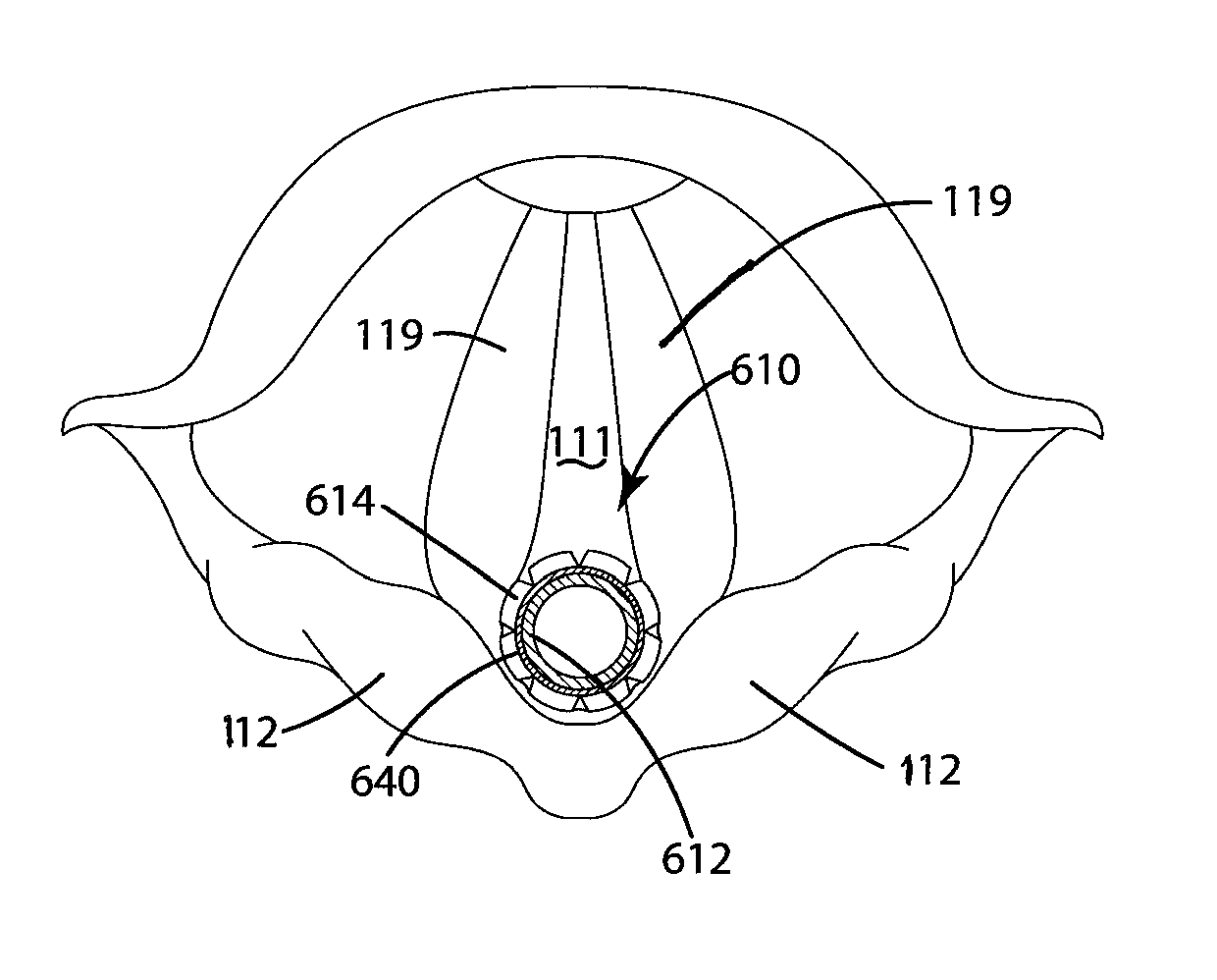
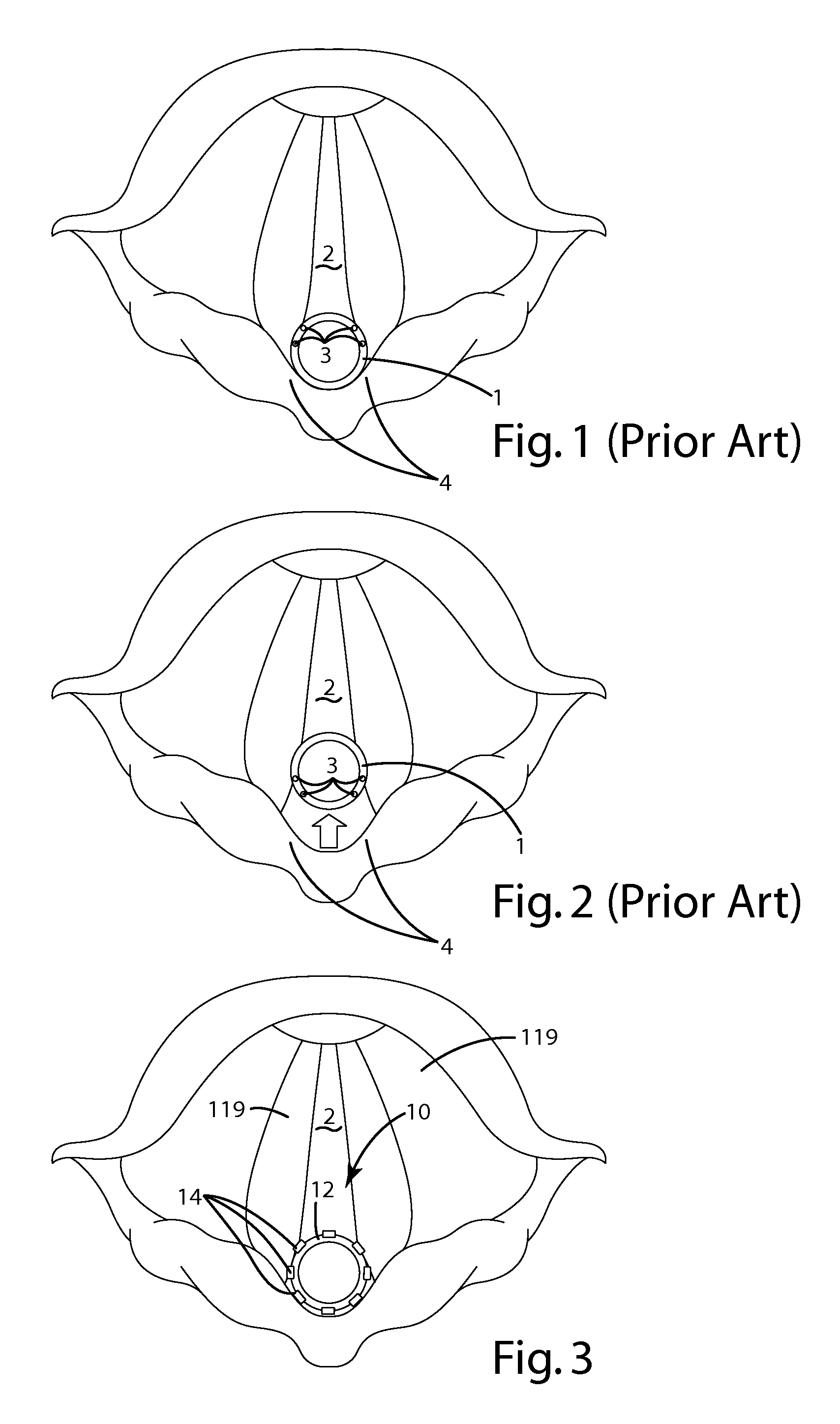
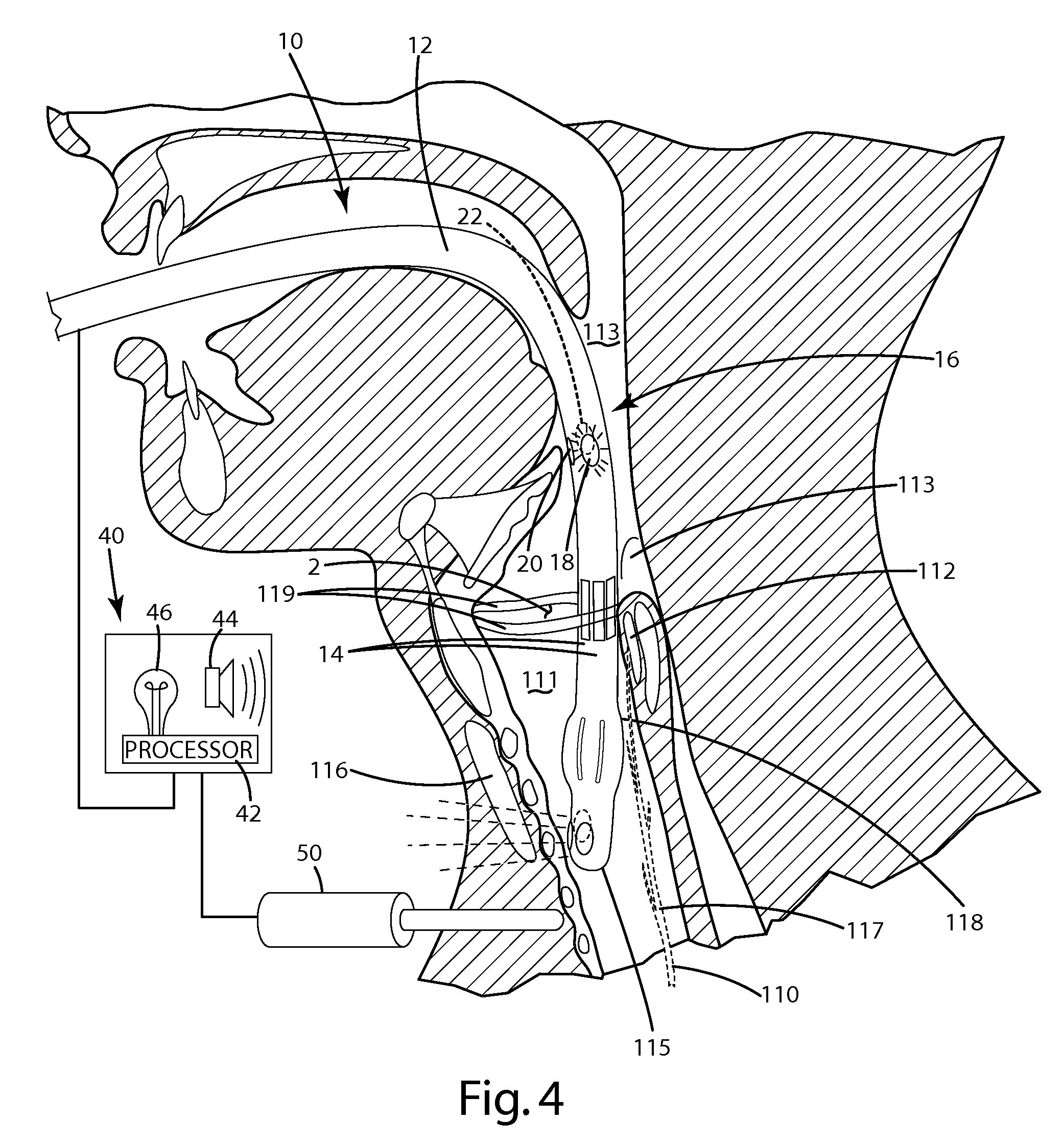
[0065]A current embodiment of the device for monitoring nerves to detect nerve and / or muscle activity is illustrated in FIGS. 3-4 and 6 and generally designated 10. The device 10 can include a cannula 12, sensor 14 and an optional output element 40, as well as an optional electrical probe 50.

[0066]In general, the sensor 14 and probe 50 can be in communication with the output element 40. As shown in FIG. 4, a surgeon can engage the probe at a location where a target nerve, such as a recurrent laryngeal nerve 110, is suspected to be located. The probe 50 provides an electrical impulse, which in turn can be transmitted through the target nerve, to an associated target muscle, such as a laryngeal muscle, for example, posterior cricoarytenoid muscles 112 and / or the vocal cords 119. The subsequent activity of the target muscle can be measured or otherwise sensed by the sensors 14, and output to the output element 40 based on the measured response. The output element 40 can output informat...


PUM


Abstract

A nerve monitoring device, including a cannula, a sensor for monitoring a nerve, and an optional support element, can be inserted into an anatomic space. The cannula, sensor and / or support element can automatically conform to and match the geometry of the anatomic space, which can enhance desired contact between the sensor and anatomic features, such as muscles, nerves or tissue in the space in an atraumatic manner. The sensor, cannula and / or support element can include one or more strips or other elements that convert from a retracted mode to an expanded mode in which the strips or elements expand, enlarge or otherwise move to match the geometry of the space and place the sensors in precise monitoring proximity relative to the target muscles, nerves or tissues. An exemplary application of the device is in the field of laryngeal monitoring, however, the device is well suited for other applications.

Description

[0001]This application is a continuation-in-part of U.S. application Ser. No. 12 / 704,303, filed Feb. 11, 2010, which (a) is a continuation-in-part of U.S. application Ser. No. 12 / 523,931, filed Jul. 21, 2009, which is the National Stage of PCT / US08 / 51768, filed Jan. 23, 2008, and which claims priority benefit to U.S. Provisional Application 60 / 886,119, filed Jan. 23, 2007, and (b) also claims priority benefit to U.S. Provisional Application 61 / 151,943, filed Feb. 12, 2009. All of the foregoing are hereby incorporated by reference.BACKGROUND OF THE INVENTION[0002]The present invention relates to nerve monitoring, and more particularly, to a device to facilitate nerve monitoring.[0003]A risk presented by thyroid surgery, parathyroid surgery, skull base surgery, cervical spine, or any other surgery in the space around the oropharynx, larynx, trachea or esophagus, is damage to the Recurrent Laryngeal Nerves (“RLN”). RLNs control the vocal cords, and damage to them can result in full or ...

Claims


Application Information

Patent Timeline
Patent Type & Authority Patents(United States)
IPC IPC(8): A61B19/00A61N1/36A61B5/04A61M16/04A61B1/267A61B5/00A61N1/05A61B5/0488A61B18/18
CPCA61B5/6853A61B5/04001A61M2205/581A61M2205/584A61M2205/583A61M16/0434A61M2205/18A61B5/6858A61B5/6859A61N1/3606A61B5/04886A61B1/267A61B5/6886A61M2230/60A61M2205/3561A61M2205/3592A61M16/04A61M16/0488A61B5/6885A61N1/0519A61B5/4041A61B5/24A61B5/394
Inventor KARTUSH, JACK, M.
Owner THE MAGSTIM
Why Eureka
Try Eureka